tobias_svensk said:n00ber, don't forget to edit that TO220-G5 footprint!
Nisbeth also had problems.
Are the pads too close togther?
Do you have the edited version? or does the other Burr Brown TO220 package work better?
Member
Joined 2002
If you have a bunch of boards you need drilled ill do it for you .. also can i get a psu board too?
They are to close yes.
Open up BUF634 in library and open device TO220-G5, the pins are 67 mil apart i think. I change that to 75-80 mil i think.
After that open up DRC in "BOARD" and "RESTRING" tab, edit the three "PADS" to something like: "min"=6mil "%"=16%
Then "LIBRARY" -> Update all
Open up BUF634 in library and open device TO220-G5, the pins are 67 mil apart i think. I change that to 75-80 mil i think.
After that open up DRC in "BOARD" and "RESTRING" tab, edit the three "PADS" to something like: "min"=6mil "%"=16%
Then "LIBRARY" -> Update all
Oh as an after thought, does the library have to be edited, even though the change in design rules seems to have the desired effect? 😕
Just a suggestion
I know that everyone has an idea what is "best" but if you are planning to make a board that will eventually be a group buy it would be nice to have pads for optional components
ideas for optional components.
Output resistor to ground (after series out resistor)
Pads between OPA output and - IN (used for a stabilizing cap or "sub" feedback resistor )
according to Ti data sheet with OPA 627, a 200pf cap must be there
OPA out to -Vs for CRD (a la n00ber)
As for me I'm only doing it for me 🙂
I have the OPA-Out to IN- as an SMD Cap. a cap 18-200pF is so small anyways so a SMD fits so much better.
As for the CRD i skipped that and using two SMD JFETs instead.
I have the OPA-Out to IN- as an SMD Cap. a cap 18-200pF is so small anyways so a SMD fits so much better.
As for the CRD i skipped that and using two SMD JFETs instead.
n00ber, no you don't if you are satisfied 🙂 but you should perhaps have some 10-12 mil between, i have about 15-18 now.
neutron7 said:Just a suggestion
I know that everyone has an idea what is "best" but if you are planning to make a board that will eventually be a group buy it would be nice to have pads for optional components
ideas for optional components.
Output resistor to ground (after series out resistor)
Pads between OPA output and - IN (used for a stabilizing cap or "sub" feedback resistor )
according to Ti data sheet with OPA 627, a 200pf cap must be there
OPA out to -Vs for CRD (a la n00ber)
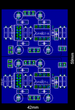
Some thing like this neutron7?
Right, time I got to bed

Thanks again for input
Craig.
Attachments
n00b, icant really see, but it looks like you have the "extra component"
between output of OPA and -supply in parrallel with ur CRD thingy
i meant between output of
OPA and - IN
sorry for confusion.
BTW great job at the out resistors.
between output of OPA and -supply in parrallel with ur CRD thingy
i meant between output of
OPA and - IN
sorry for confusion.
BTW great job at the out resistors.
To Tobias : My name is Pavel ( Paul ), the same as PMA have , you are correct 😎. Upupa Epops is latin name of one bird ( in english Hoepoe ), which is my surname ( Dudek ) 😎. And about bypassing : sound of amp make concrete connection and certainly stability by every conditions and loads. Exist only two results - stability and unstability. Every manufacturers recommend to give bypass caps as possible to rails pins, but nobody says, that if you give them far then several mm, circuit will be not functionaly in every cases, it is only Carlos's fanthasy, without any measurable proofs. " Sound of PCB " is funny and very simplify 😉 - but he like simply claiming. Not all is only black or white. 😉
neutron7 said:n00b, icant really see, but it looks like you have the "extra component"
between output of OPA and -supply in parrallel with ur CRD thingy
i meant between output of
OPA and - IN
sorry for confusion.
BTW great job at the out resistors.
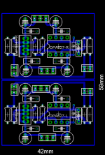
Oops! yes you are right, I have updatd my layout, thanks for that

Not your fault neutron7, it will teach me to go to bed on time 😛
I have left out the ground plane to make things easier to see😀
Thanks for the responses guy, much appreciated

Attachments
Upupa Epops said:Every manufacturers recommend to give bypass caps as possible to rails pins, but nobody says, that if you give them far then several mm, circuit will be not functionaly in every cases, it is only Carlos's fanthasy, without any measurable proofs. " Sound of PCB " is funny and very simplify 😉 - but he like simply claiming. Not all is only black or white. 😉
There are some datasheets that "scratch" this point, you just don't know how to read them.
It seems that you don't understand that most op-amps are not made for AUDIO, and the datasheets reflect this fact.
Your way of designing is good for video or other high frequency signals, but not for MUSIC.
Stable or not stable is not enough, it's a very simplistic way of seeing things.
You really have to LISTEN and compare.
Too many times I didn't replace the op-amps on a circuit, I just bypassed the op-amps in a proper way and the sound improves in a way that even a deaf guy would hear.
Like on a Krell integrated I'm working on now.
Seriously, it plays like a decent amp now (it didn't), starts to justify the original 6,000 euro (!!!!) price.😱
Call it my faltasy if you want, and live in the darkness.

Upupa Epops said:To Tobias : My name is Pavel ( Paul ), the same as PMA have , you are correct 😎. Upupa Epops is latin name of one bird ( in english Hoepoe ), which is my surname ( Dudek ) 😎. And about bypassing : sound of amp make concrete connection and certainly stability by every conditions and loads. Exist only two results - stability and unstability. Every manufacturers recommend to give bypass caps as possible to rails pins, but nobody says, that if you give them far then several mm, circuit will be not functionaly in every cases, it is only Carlos's fanthasy, without any measurable proofs. " Sound of PCB " is funny and very simplify 😉 - but he like simply claiming. Not all is only black or white. 😉
carlosfm said:
There are some datasheets that "scratch" this point, you just don't know how to read them.
It seems that you don't understand that most op-amps are not made for AUDIO, and the datasheets reflect this fact.
Your way of designing is good for video or other high frequency signals, but not for MUSIC.
Stable or not stable is not enough, it's a very simplistic way of seeing things.
You really have to LISTEN and compare.
Too many times I didn't replace the op-amps on a circuit, I just bypassed the op-amps in a proper way and the sound improves in a way that even a deaf guy would hear.
Like on a Krell integrated I'm working on now.
Seriously, it plays like a decent amp now (it didn't), starts to justify the original 6,000 euro (!!!!) price.😱
Call it my faltasy if you want, and live in the darkness.
OK, you've both made your oppinion and we are very gratefull for that as you are both quite experienced
........but please just leave it at that, we dont want another one of those threads  ...... 😉 🙂 😎
I second that🙂 It is starting to get annoying, that this cr@p is being dragged into other peoples threads. Most of us, have heard all this so many times that we are getting a bit bored😱OK, you've both made your oppinion and we are very gratefull for that as you are both quite experienced ........but please just leave it at that, we dont want another one of those threads ......
Steen.
steenoe said:I second that🙂 It is starting to get annoying, that this cr@p is being dragged into other peoples threads. Most of us, have heard all this so many times that we are getting a bit bored😱
Steen.
😡
I'll "third" that...honestly unless you have something to say that will help improve the design...or at least a pleasent way of expressing another option keep it to yourself. There are lots of ways to design a circut...and nearly as many ways to measure/evaluate them. We won't agree on these all the time but we should certainly keep an open mind.
End of my rant...now back to the preamp design 😉
maxw said:OK, you've both made your oppinion and we are very gratefull for that as you are both quite experienced
Thanks, a warning was needed.
It is always Upupa who starts these discussions, and I was only answering him.
Taking threads off-topic is his speciality.
While I try to help with some suggestions, there always jumps that guy with attacks.
NOTICE: I will always defend myself from childish attacks.
I'm beginning to get tired of all this.
My advice is: stay with him, look at his board and judge.
How can he give good advice with such a lowsy design?
I'm out now, need a rest.
I don't have any necessity to loose my time with this.
The only way how to profit from ultra short paths for bypass capacitors is to use groundplanes, otherwise inductance of PCB return paths neglects the effort. Using groundplanes is a very efficient method how to reach excellent HF PSRR, this can be easily used for preamps.
- Status
- Not open for further replies.
- Home
- Amplifiers
- Chip Amps
- GC Preamp Suggestions