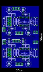
n00beR said:Here is the latest itteration
Hi n00beR, whats the point of mirror image the two channels?
Carlos, can you describe sonic results by distance of bypass caps at 1, 2, 3, 5, 10 mm ? It is thema, which will be very interesting for many guys here ( except me 😉 ).
that depends on the input impedance of the amp. the -3dB point of a first order RC highpass filter can be calculated with:
F(-3dB)= 1/(2*pi*R*C) with F in Hz, R in ohms, C in Fahrad.
ie: input impedance (R) = 22kOhm, input cap 4,7uF:
F(-3dB)=1/(2*pi*22000*4,7*10e-6) = ~1,6Hz
upupa, carlos may be a nitpicker/perfectionist and i agree with you that a difference of 1/2mm or a single 90deg corner in a supply line probably won;t make any difference at all, but if it wasn;t for him constantly hammering on things like this there'd probably be a lot of pcb design beginners (like me, fi) who'd place the caps miles away from the chips...
Exactly what i wanna know to, if someone can hear the difference if the filmcap is as close as possible and the el.cap is altered 1-2mm. Because if the el.caps fits the board better if they are 2mm further away than possible it feels like i rather have it that way.
But if the sonic difference is more than 0.01% i could be worth it?😉 or?
Please explain how much difference it make.
But if the sonic difference is more than 0.01% i could be worth it?😉 or?
Please explain how much difference it make.
Thanks Pavel (it was Pavel right?) 🙂
It was you who did that beautiful GC-PCB right?
I know i have a slight asymmetric placement of one of the el.caps on the OPA, what is your experience of that?
I mean, if i could get 90% of the performance it "could have been" i'm happy because it's the first time i'm gonna do my own pcb. And i'm only doing it for myself so... and if someone wants the files they can have them.
Oh sorry about that! 
In my mind there was two Pavels, and i thought that i had read that someone comment Upupa as Pavel.
Sorry 🙂
In my mind there was two Pavels, and i thought that i had read that someone comment Upupa as Pavel.
Sorry 🙂
Upupa Epops said:Carlos, can you describe sonic results by distance of bypass caps at 1, 2, 3, 5, 10 mm ? It is thema, which will be very interesting for many guys here ( except me 😉 ).
For the OPA627 and some others, every mm distance of the electrolythics to the PSU pins counts.
Otherwise people will say that the OPA627 has untight bass, sounds shut-in, "dark" blah blah blah...
That board, even as it is, will sound much better than yours, sorry about that.
OK sorry if this slighty off topic but seeing as everyone is talking about opamp bypass caps.
Calos I am going to replace the opamps in my Arcam Alpha 5+ CDP and was wondering what values i should use for the caps. I know that you suggest 3 caps usually. V+ to Ground V- to ground and V+ to V-. What values should i use. I have come by some 100uf 25v Back gates i was going to use for the V- to V+. And them some like 0.1uf to the to ground caps. Does this sound right?
Sorry but in a way it is on topic.
The opamps will either be ad825's ad8065's AD8610's or 627's.
I will start with the analogue device one first since i have some samles on the way.
I will mount the caps straight onto the opamp legs since you say distance is critical.
Cheers
Fil
carlosfm said:
Really, I can't see the difficulty in understanding what I'm saying.
Look at my previous post, look at the board and think.
How to avoid unnecessary corners and how to get the caps as close as possible to the PSU pins?
One hint:
Thanks calos, i know what you mean😉
Attachments
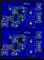
Well since everyone here is throwing around dual mono designs, here is my take on this. If you look close you will see this is the same as the stereo version that I showed earlier with the exception of the split groundplane...and no digital pot. The board that I built using this design has been up and running a few days and sounds excellent...to my ears anyway. I am using OPA637 and have had no stability problems with a gain of 8.
To keep Carlos happy the bypass caps can't get any closer to the pins, the electrolytics could likely be shifted a few mm. Also as I mentioned before this board has nearly independant power and signal grounds, they only meet at the GND connection point, essentially a power GND plane and a signal GND plane.
Your thoughts are welcome/encouraged.😉
Attachments
Member
Joined 2002
Gcollier said:Well since everyone here is throwing around dual mono designs, here is my take on this. If you look close you will see this is the same as the stereo version that I showed earlier with the exception of the split groundplane...and no digital pot. The board that I built using this design has been up and running a few days and sounds excellent...to my ears anyway. I am using OPA637 and have had no stability problems with a gain of 8.
To keep Carlos happy the bypass caps can't get any closer to the pins, the electrolytics could likely be shifted a few mm. Also as I mentioned before this board has nearly independant power and signal grounds, they only meet at the GND connection point, essentially a power GND plane and a signal GND plane.
Your thoughts are welcome/encouraged.😉
Any of your boards left over ? Id like to try one still.
j'
jleaman said:
Any of your boards left over ? Id like to try one still.
j'
I'll etch you a dual mono version and the stereo version with the digital pot tomorrow and stick em in the mail...as promised
😉 Do you need them drilled too?

Member
Joined 2002
carlosfm said:
😱
At last, something quite decent around here.😎
Pah! Post edit time ranout

It means a lot to me to receive positive input from such a respected contributer to the community as you carlos, especialy as you have a lot of exprience with this design.
Thanks a lot.
Originally posted by SvErD
Hi n00beR, whats the point of mirror image the two channels?
When I make the boards or send them for manufacture it gives me the option to mount it as one board or split it down the middle and mount two individual boards, I dont know if individal left right power ground planes has any differnce.
jleaman said:no drilling required i have a dremel : O )
jason
Well if you have a hammer and a roll of duct tape you can fix anything. 😀
I hate drilling these things and I use a drill press. You'll need a 1/32 and 3/32" bits. I'll try to put them in the mail by Monday...I'm really busy at work right now and don't have time to run to the post office.
- Status
- Not open for further replies.
- Home
- Amplifiers
- Chip Amps
- GC Preamp Suggestions