steenoe said:Very nice work, Gcollier🙂 Hope they sounds, just as good as they look.
Steen🙂
This is a mostly Gainclone forum...therefore if it looks good it MUST sound good 😉
Actually I hope to find out tonight.
G.
Hugh M said:Very Nice
Of course it will sound good. Those great big caps are naked.😉
Good work.
Hugh
Ha, Ha...they clashed with the colour scheme 😀
Member
Joined 2002
1st Listen
Well I managed to cobble together enough cables to give it a first listen...through a pair of headphones. At first I thought I screwed up because I got a nasty cycling whine...but it turns out I had connected the supply cable for the DS1802 backwards. After that It sounded pretty much transparent which is exactly what I wanted. So far I am VERY happy with the results. I could pick up no noises at all, no humm, no buzz, no hiss, just silence...except when playing music of course 😀 I'll test her out tomorrow on my parallel LM4780's
Well I managed to cobble together enough cables to give it a first listen...through a pair of headphones. At first I thought I screwed up because I got a nasty cycling whine...but it turns out I had connected the supply cable for the DS1802 backwards. After that It sounded pretty much transparent which is exactly what I wanted. So far I am VERY happy with the results. I could pick up no noises at all, no humm, no buzz, no hiss, just silence...except when playing music of course 😀 I'll test her out tomorrow on my parallel LM4780's
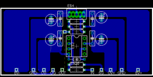
Ok here is my new and improved Brian GT inspired, single channel preamp section.
I have made this version a single layer for testing, but im still working on my double sided version. Im finding it a bit tricky as I have designed very little single sided boards never mind double sided ones.
Being single sided I was unable route one trace (the dashed yellow line) I will just jumper this with some wire.
Well, heres the image let me know what you guys think.
Cheers
Craig.
Attachments
n00beR said:Ok here is my new and improved Brian GT inspired, single channel preamp section.
I have made this version a single layer for testing, but im still working on my double sided version. Im finding it a bit tricky as I have designed very little single sided boards never mind double sided ones.
Being single sided I was unable route one trace (the dashed yellow line) I will just jumper this with some wire.
Well, heres the image let me know what you guys think.
Cheers
Craig.
Nice!
Why dont you route the trace from E$2 pin 2 on the outside of the chip and up to the resistor? then you can take the output down the center underneath E$2 and you get rid of the jumper.
Just an idea..........


All electronic industry use connectors for easy mounting and repairing. Why amateurs doesn't ? BTW, why you have on PCB so many grounds ? You need only two, signal and filtration. 😉
Member
Joined 2002
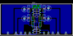
n00beR said:Finally i have finished my own design and only one jumper w00t 😀.
I think every thing is present and correct, let me know what you guys think.
Thanks in advance
Craig.
Noober,
This design looks better to me.
Attachments
Upupa Epops said:All electronic industry use connectors for easy mounting and repairing. Why amateurs doesn't ? BTW, why you have on PCB so many grounds ? You need only two, signal and filtration. 😉
It was just to make decoupling the chip supplies easier, because of the single sided layout.
WorkingAtHome said:What are you using to control the 1802 for your tests? Some simple push buttons?
Yes, I have a simple spring loaded switch that I am using for testing. I also have a set of pushbuttons removed from a broken VCR. These work fine for test purposes, but when I get around to building the chassis I will use a more elegant approach. Also if anyone would like to start throwing in ideas for a source selector feel free.
G.
Ground Loop
Hi Upopa,
I heard you said once that the grounding on PCB should not be routed as a close loop as it pick up noise. Jleaman PCB did just that. Pls comment.
Thanks.
Hi Upopa,
I heard you said once that the grounding on PCB should not be routed as a close loop as it pick up noise. Jleaman PCB did just that. Pls comment.
Thanks.
Member
Joined 2002
tobias_svensk said:
I want this : O ) Please : O )
J'
Can i have your eagle pcb file for this ? Id like to etch or get a board made up for this layout.
jleaman said:
I want this : O ) Please : O )
J'
Can i have your eagle pcb file for this ? Id like to etch or get a board made up for this layout.
I agree.. Spiffy board, especially with the RK on it. Someone get a group buy going! If they're inexpensive, I'm in for a few 😀
- Status
- Not open for further replies.
- Home
- Amplifiers
- Chip Amps
- GC Preamp Suggestions