Re: Preamp PCB Layout
Well this is all pretty new to me which should be obvious.
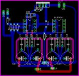
Anyway looking at the LM337 data sheet the current is actually going to the input of the LM337. Anyway, I have modified the layaout, and replaced the LM337 with an LM317. The output goes to the Vin on the LM317. If I use a 100 ohm R from out to adj on the LM317 I should get more or less 12.5 mA of bias current. As steeno suggested this may be a little high for the BUF634 DIP8 this is all I have to work with for now...so I'll just have to see if I can heatsink it 🙂
I had also looked at the CCS Table on the website noober and Alcaid mentioned, but was misinterpreting how to incorporate them. After looking back at Tangents site and refering to the CCS table I think I have it right now...please by all means correct me if I don't.

Alcaid said:
Isn't the normal way to do it to draw the current from the opamp's output to the negative rail? Not feed the current.
Check this out:
http://www.headphoneamp.co.kr/bbs/zboard.php?id=diy_sijosae&no=211
Lot's of CCS examples. Text is not in english but you get the schematics and numbers...
Well this is all pretty new to me which should be obvious.
Anyway looking at the LM337 data sheet the current is actually going to the input of the LM337. Anyway, I have modified the layaout, and replaced the LM337 with an LM317. The output goes to the Vin on the LM317. If I use a 100 ohm R from out to adj on the LM317 I should get more or less 12.5 mA of bias current. As steeno suggested this may be a little high for the BUF634 DIP8 this is all I have to work with for now...so I'll just have to see if I can heatsink it 🙂
I had also looked at the CCS Table on the website noober and Alcaid mentioned, but was misinterpreting how to incorporate them. After looking back at Tangents site and refering to the CCS table I think I have it right now...please by all means correct me if I don't.
Attachments
Using a voltage regulator as a current bias is likely to induce a lot of noise. Common regs like the 317 are by no means 'quiet'. You may also find that their response to audio frequencies is very poor. They're really designed for the frequencies you get from rectified mains. You will be much better off with 1 or 2 transistors / JFETS in terms of the bandwidth of your CCS, and noise currents.
TwoSpoons said:Using a voltage regulator as a current bias is likely to induce a lot of noise. Common regs like the 317 are by no means 'quiet'. You may also find that their response to audio frequencies is very poor. They're really designed for the frequencies you get from rectified mains. You will be much better off with 1 or 2 transistors / JFETS in terms of the bandwidth of your CCS, and noise currents.
Honestly I won't know how much noise this introduces until I try it, but I don't think it will be all that bad. I have heard that it can add 0.003% noise from somwhere in the Headwize forum, which is sounds pretty low. Also the banwidth of the LM317 is something like 100kHz so I doubt it will have a problem with audio frequencies, in fact it can be used as an audio amplifier (see the datasheet). Anyway I'll give it a try and if it is too noisy I will go the JFET route...or maybe just a simple resistor.
I will likely etch a sample board and give it a listen over the weekend...I think I have all the parts sitting around.
It just struck me as odd that you would go to all the effort of biasing into class A, then do it with a poor component (compared to a BJT or FET ccs).
" 0.003% noise" : 0.003% of what? What is the actual rms noise current and noise voltage?
Incidently, instead of all that 'star-pointing' on your ground tracks, you'd be better simply to use a ground plane over the entire board.
" 0.003% noise" : 0.003% of what? What is the actual rms noise current and noise voltage?
Incidently, instead of all that 'star-pointing' on your ground tracks, you'd be better simply to use a ground plane over the entire board.
TwoSpoons said:It just struck me as odd that you would go to all the effort of biasing into class A, then do it with a poor component (compared to a BJT or FET ccs).
" 0.003% noise" : 0.003% of what? What is the actual rms noise current and noise voltage?
Incidently, instead of all that 'star-pointing' on your ground tracks, you'd be better simply to use a ground plane over the entire board.
I may in fact go the FET route in the end anyway, but I really just want to try and see if the LM317 functions well in this type of application. The output current should be very steady over a wide input range when using an LM317. Anyway I am likely going to redraw the board to include solder points for a number of different biasing options.
As for your comments regarding a groundplane..there is in fact one there, the large blue rectangle that surrounds the entire board is a groundplane on the underside of the board that I have "riped up" in Eagle, so that it is easier to see what is routed where. The topside will also have a copper pour but I dont intend on connecting it to anything...perhaps earth ground.
Anyway thanks for the comments, I'll take all the help I can get!
🙂
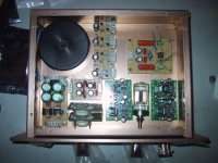
The Chip preamp is getting along. Have a look at the initial setup.
The boards are to the left 317/337 main psu witch feeds the LED regulator of Nuuk's next to the trafo. That will feed the linestage and the VSPS riaa. The main psu also feeds Alcaids CCS/Zener regulator that will feed the headphone amp in lower right corner.
After the great experience with CarlosFM's mods on PMA's schematic,I decided to implement Carlos's ideas on Pavels cute little PCB's. I managed to get 100uF on the OPA's bypass. And the 200pico Polyprop is soldered in, underneath the cute little boards. Elma attenuator with SMD decks and Elma input selector.
The headphone socket is Neutrik. Two boards not quite finished, the VSPS phonostage and Alcaids regulator, but that will be soon. Just received the J511 CCS's today. I want this to be a complete preamp so it can act as a stand-in when modding on the main system. R11 on PMA's boards are replaced by a jumper so the buf's will run in class A up til about 3volts peak. The Gain is set to about +2.47 volts. Hope this one will sound as good as the perfboards I made earlier🙂 Hope you can use some ideas Gcollier.
Steen.
Attachments
Member
Joined 2002
steenoe said:The Chip preamp is getting along. Have a look at the initial setup.
The boards are to the left 317/337 main psu witch feeds the LED regulator of Nuuk's next to the trafo. That will feed the linestage and the VSPS riaa. The main psu also feeds Alcaids CCS/Zener regulator that will feed the headphone amp in lower right corner.
After the great experience with CarlosFM's mods on PMA's schematic,I decided to implement Carlos's ideas on Pavels cute little PCB's. I managed to get 100uF on the OPA's bypass. And the 200pico Polyprop is soldered in, underneath the cute little boards. Elma attenuator with SMD decks and Elma input selector.
The headphone socket is Neutrik. Two boards not quite finished, the VSPS phonostage and Alcaids regulator, but that will be soon. Just received the J511 CCS's today. I want this to be a complete preamp so it can act as a stand-in when modding on the main system. R11 on PMA's boards are replaced by a jumper so the buf's will run in class A up til about 3volts peak. The Gain is set to about +2.47 volts. Hope this one will sound as good as the perfboards I made earlier🙂 Hope you can use some ideas Gcollier.
Steen.
Im interested in some of the things you built into your chassis can you give me some explanation of what you have in there ? oh good job on the case looks great!!
steenoe said:... And the 200pico Polyprop is soldered in, underneath the cute little boards...
If I where you I would use a smaller value than 200pf. I don't know what value you use for the feedback resistor, but with a 3k3 resistor there, look what the 200pF cap does to the phase. Don't know if it's audible, but if your Rf is bigger, you have even more problems.
Attachments
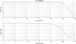
Hmmm, interresting curves, Alcaid. I see your point. CarlosFM was quite persisting on the value of 200p. Come to think of it, I remember Pavel recommended 18pF. I think I will lower the value as it quite easy at this point, thanks for the pointer🙂 Great to have you guys aroundIf I where you I would use a smaller value than 200pf.
😉
I will try! As for the psu it might seem to be a lot of fiddling with a simple thing.Im interested in some of the things you built into your chassis can you give me some explanation
But for a preamp I am convinced that it pays to have a good and stable supply. I was a bit concerned that Nuuks regulator wasn't able to deliver enough current to all the boards so I decided to try Alcaids beautifull CCS/Zener regulator to supply the headphone amp. I think that is the most current demanding circuit in there. It is the small board right above the attenuator.
Otherwise the mainsupply is a fairly regular LM317/337 regulated supply with 21 volts output. The two following regulators takes the voltage down to 16,5 volts, wich I was aiming for. The rest of the circuits in there is Pavels nice little pcb's, the green ones. One for the linestage and one for the headphone amp. The perfboard on the right upper is the VSPS phonostage. (Very Simple Phono Stage) (As simple as they come) I wanted the El-Cheapo but couldnt fit it in the small case. If you need more information or links to the particular circuits, let me know.
😎
Steen.
BTW, just read my reply further up and realised this was not very elegantly put:
Steen.
I meant ofcourse something like this: Hope you can use some of the ideas🙂Hope you can use some ideas Gcollier.
Steen.
Ï can't take all the credit for the CCS/Zener+Emitter follower regulator, because I got a lot of help from people here at this forum.
http://www.diyaudio.com/forums/showthread.php?s=&threadid=33191&perpage=10&highlight=&pagenumber=1
It was actually the first circuit I ever buildt. Have learnt a lot since that, but still got almost everything left to learn 😉
I'm a petroleum engineer student, not EE I'm afraid 🙁
http://www.diyaudio.com/forums/showthread.php?s=&threadid=33191&perpage=10&highlight=&pagenumber=1
It was actually the first circuit I ever buildt. Have learnt a lot since that, but still got almost everything left to learn 😉
I'm a petroleum engineer student, not EE I'm afraid 🙁
You are not better of than me then😀 I am a Reprotechnician with no knowledge of electronicsI'm a petroleum engineer student, not EE I'm afraid
 Well, almost
 The great thing about this forum in a nutshell: what you do not know, somebody else does. Great. There is more than 30.000 members on this forum😉
 Steen.
Yep.
BTW. Where did you buy that case? I've bougt mine from par-metal (Series 20) and they're nice but always looking for options for all those hundreds of projects going around in my head 🙂
BTW. Where did you buy that case? I've bougt mine from par-metal (Series 20) and they're nice but always looking for options for all those hundreds of projects going around in my head 🙂
I bought the case here: http://www.thlaudio.com/
In fact I buy a lot of the hardware there. Mr. Vincent Chang is a reliable fellow and I have never experienced any problems, dealing with him. I will post a few more pics of some of the things from there.(Taiwan) Incredible prices 🙂 The chassis are very well made, like the rest of the hardware from there. First a pic of my OPA549 chipamp.
In fact I buy a lot of the hardware there. Mr. Vincent Chang is a reliable fellow and I have never experienced any problems, dealing with him. I will post a few more pics of some of the things from there.(Taiwan) Incredible prices 🙂 The chassis are very well made, like the rest of the hardware from there. First a pic of my OPA549 chipamp.
Attachments
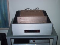

I saw the opa549 amp was lying on top of your living-room heater. 😉
Is it to heat up the opa549's to make a warmer class-a sound?
Is it to heat up the opa549's to make a warmer class-a sound?
Yes, the OPA549 sounds absolutely better that way😉 Alcaid, you being a student makes me want to help out a little. If you want in, next time I order from Taiwan send me a mail😎Is it to heat up the opa549's to make a warmer class-a sound?
Steen.
steenoe said:Yes, the OPA549 sounds absolutely better that way😉 Alcaid, you being a student makes me want to help out a little. If you want in, next time I order from Taiwan send me a mail😎
Steen.
I'm actually drewling on the site right now. It's mekka for the diyaudio hobyist....
You are right🙂 The company is very honest and reliable. Everything is handled most proffesionally by the owner Mr. Chang. More members on this forum ought to use this source, IMHO. He has the right stuff at the right prices🙂 Postage isnt't to bad either.It's mekka for the diyaudio hobyist....
Highly recommended! Hmmm, but this is a bit off thread isn't it?
Nonetheless, I would like to spread this source to all DIYaudio- members.
Steen.
I apologize for taking this even further off topic. 😱
Alcaid, there is a group buy going on for a chassis which looks very similar. It's not available in the nice champagne color unfortunately. Here's the link: http://www.diyaudio.com/forums/showthread.php?s=&threadid=51122 . The 100mm model is the one I'm talking about. In fact, I believe that is also being sourced from Taiwan. 😀
Alcaid, there is a group buy going on for a chassis which looks very similar. It's not available in the nice champagne color unfortunately. Here's the link: http://www.diyaudio.com/forums/showthread.php?s=&threadid=51122 . The 100mm model is the one I'm talking about. In fact, I believe that is also being sourced from Taiwan. 😀
- Status
- Not open for further replies.
- Home
- Amplifiers
- Chip Amps
- GC Preamp Suggestions