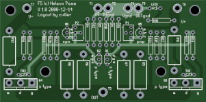
Why not two more holes instead of one ?
You could add the first below R14/20/22, the second below R21/19/17. More stable on four legs... 😉
You could add the first below R14/20/22, the second below R21/19/17. More stable on four legs... 😉
hi cviller,
i virtually stuffed the boards, but was not able to fix the termistors right next to the middlepin of the output transistors. Do you suggest to fix both from the downside?
nice work, thanx
stefan
i virtually stuffed the boards, but was not able to fix the termistors right next to the middlepin of the output transistors. Do you suggest to fix both from the downside?
nice work, thanx
stefan
korben69 said:Why not two more holes instead of one ?
You could add the first below R14/20/22, the second below R21/19/17. More stable on four legs... 😉
I agree. I weren't really happy about he placement of the third hole anyways. I'll change it and post another picture.
cviller:
I noticed that you had <Aaron Blossom> as paid. Please note that <Aaron Blossom> and pblossom (as on the Wiki) are one and the same.
Thanks
I noticed that you had <Aaron Blossom> as paid. Please note that <Aaron Blossom> and pblossom (as on the Wiki) are one and the same.
Thanks
noelectrix said:hi cviller,
i virtually stuffed the boards, but was not able to fix the termistors right next to the middlepin of the output transistors. Do you suggest to fix both from the downside?
nice work, thanx
stefan
Thanks for doing a test stuffing!
I'm not completely sure what the problem is. Are the thermistor legs touching the mosfet legs? Or is it only a problem of getting the alignment spot on?
pblossom said:cviller:
I noticed that you had <Aaron Blossom> as paid. Please note that <Aaron Blossom> and pblossom (as on the Wiki) are one and the same.
Thanks
I mark paypal names in <> if I'm unsure about the diyname. Now I know! 😉
cviller said:I'm not completely sure what the problem is. Are the thermistor legs touching the mosfet legs? Or is it only a problem of getting the alignment spot on?
I´m sure it will also fit this way. But with the termisor "behind" the transistor it is more suitable for "right angle" mounting to the aluminium block. FOr mounting the board parallel with the transie stuffed from the bottom of the board, the termistor has to "cross" the transistor legs somehow. But no sweat. Maybe i´m on the wrong way there and "just "near-to-the-transistor-mounting is perfect.
s.
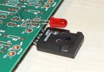
And another thing: If you look at papas solution: http://6moons.com/audioreviews/firstwatt7/f5_2.html the thermistor does not need to be all that close to the mosfet die. In fact you might even mess up the thermal feedback loop if you do the connection too well. 
cviller said:And another thing: If you look at papas solution: http://6moons.com/audioreviews/firstwatt7/f5_2.html the thermistor does not need to be all that close to the mosfet die. In fact you might even mess up the thermal feedback loop if you do the connection too well.
Didn't Nelson suggest gluing the thermistor to the MOSFET?
labjr said:
Didn't Nelson suggest gluing the thermistor to the MOSFET?
I haven't read the whole thread. He might have suggested that - i doubt ringing is a problem in this regulation... 😀
I have uploaded a new layout - I still plan on ordering tonight, unless someone points out a blocking issue with my layout.
Attachments
labjr said:No rush. I'd rather have it done right than have to redo it because something got overlooked.
Good point.
My flow from schematics to pcb have over the years proven to be very stable, in fact I have not tried to have an error in pcb which was not already in schematics. If anyone has the time to double check my schematics against the original I would appreciate it.
Attachments
cviller said:
I mark paypal names in <> if I'm unsure about the diyname. Now I know! 😉
In that case, diy user grenert is the same as James Grenert on the paid list.
Thanks for doing this!
Re: Got a question about components for the PSU
Guys, what's the disadvantage of using a little less capacitance?
I noticed some used just 30,000uf per channel on their F4's.
Kind of wondering how low one can go and still have a fairly quiet and robust power supply. If I go too low, I assume peaks in output will suffer, but I don't really know.
Christian the boards look really nice.
Mike
cviller said:The layout I have made here is for the standard firstwatt style psu. So you'll need:
Onboard:
8 x snap in caps (at least 25V and 15mF more is better)
8 x 0.47 ohm 3W resistors
2 x 2.2k 3W resistors (for discharging caps)
Off board / somewhere else:
2 diode bridges mounted somewhere on the chassis
1 toroid 2x18 300VA
1-2 thermistors for soft starting the toroid
switches, connectors, fuses and all that stuff
This will be enough for a stereo amp or a monoblock, but remember diy people always want to go over the top. 😉
Guys, what's the disadvantage of using a little less capacitance?
I noticed some used just 30,000uf per channel on their F4's.
Kind of wondering how low one can go and still have a fairly quiet and robust power supply. If I go too low, I assume peaks in output will suffer, but I don't really know.
Christian the boards look really nice.
Mike
cviller said:
I mark paypal names in <> if I'm unsure about the diyname. Now I know! 😉
<Jim Tremain> is jimt
Thanks
Re: Re: Got a question about components for the PSU
I'm not sure how low you can go before affecting the performance. I think the more you have the better though. Why not use at least what's in the original circuit? Better bass etc. I think historically Nelson has designed power supplies with lot's of capacitance. I remember reading about it in Threshold brochures twenty or thirty years ago.
I know people who have two farads in their cars.
mithomas said:
Guys, what's the disadvantage of using a little less capacitance?
I noticed some used just 30,000uf per channel on their F4's.
Kind of wondering how low one can go and still have a fairly quiet and robust power supply. If I go too low, I assume peaks in output will suffer, but I don't really know.
Christian the boards look really nice.
Mike
I'm not sure how low you can go before affecting the performance. I think the more you have the better though. Why not use at least what's in the original circuit? Better bass etc. I think historically Nelson has designed power supplies with lot's of capacitance. I remember reading about it in Threshold brochures twenty or thirty years ago.
I know people who have two farads in their cars.
R21 and R22 was later changed to 22k.
http://www.diyaudio.com/forums/showthread.php?postid=1643840#post1643840
🙂
http://www.diyaudio.com/forums/showthread.php?postid=1643840#post1643840
🙂
steenoe said:R21 and R22 was later changed to 22k.
http://www.diyaudio.com/forums/showthread.php?postid=1643840#post1643840
🙂
Thanks. I'll change that in the schematics, but the layout remains the same. 😉
labjr said:two farads
Farad numbers mean squat without the operating voltage.
The common approach to scale capacitor size in the power supply of a Class AB amplifier is the required number to keep the voltage ripple sufficiently low at full output power.
The cap bank of a Class A amplifier needs to be larger to keep ripple low at idle, due to the high bias level.
A Japanese manufacturer would regulate the front stage rails, employ higher PSRR, and stick less uF in the power supply.
Another approach is to look at the energy stored in the lytics, compared to the continuous output power level.
Some like it to be at least Joule to Watt equivalent, boils down to a minimum of 80.000uF at 25Vdc per channel for an F5.
- Status
- Not open for further replies.
- Home
- Group Buys
- Gb: F5 Pcb