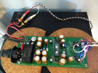
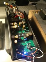
With R103/107 in place and R4; R203/207 out the circuit settles at 24.04 volts after 20 seconds.
With R103/203 and R107/207 but no R4 the voltage is unstable and does not go above 10 volts 😕
With R103/203 and R107/207 but no R4 the voltage is unstable and does not go above 10 volts 😕
1/2 Done but sounds GREAT!
Sorry it took so long to post some 1/2 done pics but I'm finishing three projects right now.
Currently I am enjoying this, mostly done NuTube through a freshly built Aleph J amp. WOW! is all I can think or say. Seriously I'm stunned at the detail this tube is capable of producing. Currently I have the bias set a 10.0 volts. I have had it as high as 10.5 volts which is nice for a cd input. Right now i am enjoying Johnny Cash Amerirican Recordings on vinyl and Johnny sounds like he's in the room! The buzz of partially depressed strings has never sounded so sweet or clear.
Thanks Algar-emi for a Great Board!
Attachments
Just made a small order for a late buyer weeks ago. I still have a few to sell. Send me a private email if interested...
SB
SB
Still a few extra pcb left. Send me an email if interested. This last batch has the small pcb errors corrected and much larger spacing between L and N traces as recommeded by some members, so it should work perfectly out of the box. Numerous builders confirm so far that the PCB is correct. Thanks
SB
SB
Hi Algar,
I have a few questions for you...
- I have Rev1.4 of the PCB and was wondering if post 119 and 121 issues were fixed?
- I'm using J113 from Pass kit in DIYaudio store (came with J-R1 as well). I tested the PSU before adding R107, 103, 207, and 203 and the PSU voltage were just fine. Added R107, 103, 207, and 203 and then SMPS has started to pulse, 5V pulses. This means there is possibly a short. Now that the parts in place, I cannot see the traces properly. Seems like there is a possible pinout/traces wrong on the J113. Could you please look into it?
Anyone has done J113 assembly?
Thanks
Do
I’ve done it with the J113 JFETs from the store kit. Power supply and left channel perfect. Issue with the right channel I’m having difficulty finding time to solve.
Mine is just SMPS pulsing 5-6 Vdc on and off as if the output is over-current or shorted, but it is not shorted... Just wondering if there's too much capacitance on the output of the SMPS. They sometimes do that... I will remove the SMPS module and power it using my lab bench PSU.
Algar, any other hints?
Thanks
Do
Algar, any other hints?
Thanks
Do
I've seen some SMPS behave just as you stated when trying to charge a large capacitor bank. Some are more tolerant than others, depending on their fault-protection logic. Testing with your bench supply is the best path.
Yes, and in this case, this SMPS is having a hard time charging those caps with the load attached. Trying with the bench supply I can get things working and voltages are reading fine.
Algar_emi, did you get everything running with that SMPS and the caps in your BoM or did you have to change cap values and lower the total capacitance?
My bench supply seems to indicate ~75mA with everything working at 23.98Vdc. If that is the case, maybe I need to leave the SMPS pulse for much longer but it does not seem to be able to charge more than 5-6Vdc.
I'll put everything under sine wave and see on the scope if it is properly alive.
Do
Checked everything on the scope with my Freq. generator and both channels look very good, even square wave is not bad at all for tube!
I used a similar meanwell module, the IRM-20-24, which worked fine for me. It cost a little less too because it is not classed as a medical device rated.
GB B1 Nutube PCB with integrated PS
GB B1 Nutube PCB with integrated PS
- Home
- Group Buys
- GB B1 Nutube PCB with integrated PS

