Mad_K said:I see😉 There has been little response, so either people are getting it all, or it is not interesting.
Hi!
Very interresting reading, so please keep posting.
I have a bunch of 549 laying around, so maybe when your project is finished...................................
So much to do, and so little time.............. And a family who whants to bee a part of my life as well.😉
Tor Martin
Tor M said:
so maybe when your project is finished...................................
It is finished all the time, I'm just playing around 😉
Or you can say It'll never be finished. That's the beauty of gaincloning me thinks.
So much to do, and so little time..........
-Yepp, that's life in a nutshell

Dear Mad man,
We are lurking and enjoy hearing about your progress. I especially appreciate your clear schematics. When I finish my Pass balanced line source I will probably need this circuit.
We are lurking and enjoy hearing about your progress. I especially appreciate your clear schematics. When I finish my Pass balanced line source I will probably need this circuit.
Thanks Variac 😉
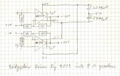
All the 100K's (except feedback) in the above schematic can be skipped. The 100K on the DRV134 can be replaced by a log pot to be driven directly (also add a 2uF cap in series). To null out DC-offset (not likely to be a problem), a 200K pot to S gnd can be placed on the +in on all opa's. Ofcourse, this can also be done with the 8 ohm version.
All the 100K's (except feedback) in the above schematic can be skipped. The 100K on the DRV134 can be replaced by a log pot to be driven directly (also add a 2uF cap in series). To null out DC-offset (not likely to be a problem), a 200K pot to S gnd can be placed on the +in on all opa's. Ofcourse, this can also be done with the 8 ohm version.
Well, I HAD to put it back in...
After another week of listening impressions, I am a little bit more educated😉 This week we got the new ZV5, and ofcourse some time has been spent studying that design. This also led me to read the A75 article again, wich explain in great detail the details around a balanced input. (Ref "Gang of Four" page 12 A75 part1). This confirms that my circuit is indeed correct.
I have also found my absolute preference in both chip type and circuit configuration. This is the minimal OPA541 circuit shown here: http://diyaudio.com/forums/showthread.php?postid=198895#post198895
But with a 1uF added between V+/V- on the chip's pins. Note that it is unwise to power it up without a source connected, as it can become unstable (only happened with LM chips though). DC offset with BZLS connected is 5-10mV.
In the light of the ZV5's 600ohm input impedance, I also tried a version with opa541 and 1K input Z (1K input, 10K feedback). The BZLS just cruised into it, albeit with a little reduced gain.
The difference between the bridged opa549 circuit, and the minimal opa541 circuit can be very different depending on all the other factors in your system and your mind. For instance, if your speakers require lots of power the bridge circuit wins hands down. Likewise if you like to listen at high levels and complex music. But if you have sensitive speakers, and/or listens to more moderate listening levels the minimal opa541 circuit is much better. With less complex music (for example Ben Harper's "Welcome to the Cruel World" like I'm listening to right now), the mbgc/541(Minmal Balanced GainClone with OPA541 ;-) is much better. Note that I listen to a VERY broad range of music like Metallica, Spongle, DMB, Lisa Ekdahl, Fu Manchu, Kyuss, The Cardigans etc etc. So in my room , with my setup, and my listenig habbits, I prefer the mbgc/541 🙂. It flattens out at absolute party levels, but by then I'm usually pleasantly sedated, so it doesn't matter much.
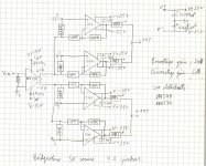
Here's a snapshot of the mbgc/541 with 1K/10K resistors. I've changed it back to 10K/100K now, because I only have 10uF coupling caps in my BZLS. (I'm going to change them for a more complex composite quad-cap setup soon).
-Keep on Tweaking!
After another week of listening impressions, I am a little bit more educated😉 This week we got the new ZV5, and ofcourse some time has been spent studying that design. This also led me to read the A75 article again, wich explain in great detail the details around a balanced input. (Ref "Gang of Four" page 12 A75 part1). This confirms that my circuit is indeed correct.
I have also found my absolute preference in both chip type and circuit configuration. This is the minimal OPA541 circuit shown here: http://diyaudio.com/forums/showthread.php?postid=198895#post198895
But with a 1uF added between V+/V- on the chip's pins. Note that it is unwise to power it up without a source connected, as it can become unstable (only happened with LM chips though). DC offset with BZLS connected is 5-10mV.
In the light of the ZV5's 600ohm input impedance, I also tried a version with opa541 and 1K input Z (1K input, 10K feedback). The BZLS just cruised into it, albeit with a little reduced gain.
The difference between the bridged opa549 circuit, and the minimal opa541 circuit can be very different depending on all the other factors in your system and your mind. For instance, if your speakers require lots of power the bridge circuit wins hands down. Likewise if you like to listen at high levels and complex music. But if you have sensitive speakers, and/or listens to more moderate listening levels the minimal opa541 circuit is much better. With less complex music (for example Ben Harper's "Welcome to the Cruel World" like I'm listening to right now), the mbgc/541(Minmal Balanced GainClone with OPA541 ;-) is much better. Note that I listen to a VERY broad range of music like Metallica, Spongle, DMB, Lisa Ekdahl, Fu Manchu, Kyuss, The Cardigans etc etc. So in my room , with my setup, and my listenig habbits, I prefer the mbgc/541 🙂. It flattens out at absolute party levels, but by then I'm usually pleasantly sedated, so it doesn't matter much.
Here's a snapshot of the mbgc/541 with 1K/10K resistors. I've changed it back to 10K/100K now, because I only have 10uF coupling caps in my BZLS. (I'm going to change them for a more complex composite quad-cap setup soon).
-Keep on Tweaking!
Attachments
Henrik said:Mads
You shoud try to X your BZLS (BOSOZ), it´s simple to do, just a couble of ressitors, and I think your balanced GC might benefit from it.
I am interested in your pseudobalanced GC, an have just read the posts from Torsten that you pointed out. Thanks. I have the parts to build it, but it might take some time for me to make it, I am not a full time DIY´er and I also have other audio projects.
As I now feel I have exhausted/tweaked this amp to a performance level I'm comfortable with it's time to do something else... Your X circuits comes to mind. I will start by making my BZLS into your ZBOSOZ. It's a little more than just popping in a few resistors, 'cause I have the volume pot at the output, but I'll certainly do it. As I am in the design-phase of my new dual-mono 15W SOZ with air-cooled (passive) Danotherm GRF resistors, I think I'll make it an XSOZ following your schematics from post #242 in the XSOZ thread (there aren't any new updates I need to be aware of?)
Hi Mad_K
I have missed your last posts in this thread, sorry.
I have no upgrades for the XSOZ, it still plays butifull as is, an I believe it´s difficult to do it otherwise as long as you wants it to stay Zen.
I am eager to read about your expieriences with your GC and XSOZ.
15W XSOZ, wow!
But I am going on hollyday tomorrow morning, and will be gone for a month, so if I am not replying to your posts then you know why.
Happy building.
Regards Henrik.
Member
Joined 2002
Dear mads!
Could you make a redraw of your last schematic for the OPA549/-541, with all your updates - 4 an 8 ohm's schematic - just for me?
You guys use so many shortning - BZLS, ZBOSOZ, XSOZ - What do they mean?
I have spend several months, every night for 2 - 3 hours, reading posts here in diyaudio - I am new to all this, but I want to learn!
Per
Re: Well, I HAD to put it back in...
Something seems to be wrong on the URL because it doesn't take me anywhere. Can you check that?
Where can I find the BZLS circuit?
Carlos
Mad_K said:
I have also found my absolute preference in both chip type and circuit configuration. This is the minimal OPA541 circuit shown here: http://diyaudio.com/forums/showthread.php?postid=198895#post198895
But with a 1uF added between V+/V- on the chip's pins. Note that it is unwise to power it up without a source connected, as it can become unstable (only happened with LM chips though). DC offset with BZLS connected is 5-10mV.
Something seems to be wrong on the URL because it doesn't take me anywhere. Can you check that?
Where can I find the BZLS circuit?
Carlos
Re: Re: Well, I HAD to put it back in...
Original BZLS is here:
http://passdiy.com/legacy.htm
the link seems to be working for me....
carlmart said:
Something seems to be wrong on the URL because it doesn't take me anywhere. Can you check that?
Where can I find the BZLS circuit?
Carlos
Original BZLS is here:
http://passdiy.com/legacy.htm
the link seems to be working for me....
pip said:Dear mads!
Could you make a redraw of your last schematic for the OPA549/-541, with all your updates - 4 an 8 ohm's schematic - just for me?
You guys use so many shortning - BZLS, ZBOSOZ, XSOZ - What do they mean?
I have spend several months, every night for 2 - 3 hours, reading posts here in diyaudio - I am new to all this, but I want to learn!
Per
-I'd love to redraw schematic's, but I'm in Chicago on a vacation right now so it'll have to wait a few weeks. Basically I have 3 schematics: 8 ohm balanced input(1*opa541/ch), 8ohm bridged (2*opa549/ch), and 4ohm bridge+paralell (4*opa549/ch).
Balanced Zen Line Stage
X Bride Of Son Of Zen (=XBZLS)
X Son Of Zen
try some searches with these shortings
😉
Mad K, where'd you get your amp cases?
I've been following this thread and have to say congratualtions and thanks for posting your adventures. I'm ordering parts this week to make a copy of Joe Rasmussen's(Sp?) Tube-buffered inverted GainClone (derived from more of Kui's work).
Anyway, I'm looking for a good chassis to house it all. And how much do they cost?
Thanks for all the work,
Darkmoebius
MADK I'd love to see your schematics!
"-I'd love to redraw schematic's, but I'm in Chicago on a vacation right now so it'll have to wait a few weeks. Basically I have 3 schematics: 8 ohm balanced input(1*opa541/ch), 8ohm bridged (2*opa549/ch), and 4ohm bridge+paralell (4*opa549/ch)."
MadK
I just purchased a couple of OPA541s for experimenting. I'd love to see the schematic for the balanced circuit you mentioned above. I think it's the one I'd like to try. Are you back from Chicago?
Eagerly anticipating my own balanced GC.
-Erik.
Question for Joe Dirt
Hey Joe, how you may to say about work showed on photo that is " nice " ? Similar work by us is called " pig's work ". If you will always applaud to the similar things. this boy never will do better. My words are so hard, but I mean it in good.
Hey Joe, how you may to say about work showed on photo that is " nice " ? Similar work by us is called " pig's work ". If you will always applaud to the similar things. this boy never will do better. My words are so hard, but I mean it in good.
Re: Question for Joe Dirt
Show us some of your work and maybe than you will gain more credibility😉
Upupa Epops said:Hey Joe, how you may to say about work showed on photo that is " nice " ? Similar work by us is called " pig's work ". If you will always applaud to the similar things. this boy never will do better. My words are so hard, but I mean it in good.
Show us some of your work and maybe than you will gain more credibility😉
Upoopa:
It's nice because he is a do-er not a talker or complainer.
It's good work because he is adventurously discovering
stuff. Exactly copying an existing circuit into a pretty box with pretty and neat wiring is a lower level of DIY Audio IMHO
It's nice because he is a do-er not a talker or complainer.
It's good work because he is adventurously discovering
stuff. Exactly copying an existing circuit into a pretty box with pretty and neat wiring is a lower level of DIY Audio IMHO
- Status
- Not open for further replies.
- Home
- Amplifiers
- Chip Amps
- Gainclone with pseudo-balanced input?