The reason of doing this kind of DC offset test is to make sure there is low DC or even no DC voltage go to the speakers because DC will kill your driver faster than a kid ploking, fire crackers (I forget who said this before, anyway it is from him.) Try to imagine/test the some useless driver with a 1.5V battery, you will see the cone is only going all the way to either out or in. DC voltage form amplifier does the same thing, and it is worse cuz it will burn the voice coil. 😉 Man, I hope mine have a DC off set like your's. 
S.C.
Exactly the reason I measured them without connecting to any speakers first. Anyway every chip is different so may be I am just lucky to have a lowerish DC offset chip from BrianGT this time round. May be your next one will be better?
Regards,
Chris
Exactly the reason I measured them without connecting to any speakers first. Anyway every chip is different so may be I am just lucky to have a lowerish DC offset chip from BrianGT this time round. May be your next one will be better?
Regards,
Chris
Pls Help2
Well I didn't make any progress tonight. I put in some new fuses fired her up and........nothing. No sparks, no smoke, no voltage!!!
I'm not sure what to do next. I'm afraid the Black Gates are the culprit now. I guess I could try the other power supply board..but I'm afraid to since I don't know what was wrong the 1st time. Any suggestions?
Help
Jimmy and Kestrel200,
In order for people to give you help, please help us to understand your situation by providing more precise information about your projects. How you wired it up, clear pics/ hand draw diagrams will help, steps that you have taken or events that occured. I think we all hate to leave you in the dark, but unfortunately we can not help you in the dark ourselves as well.
Please do not give up. I am sure some of our more experienced members will be glad to help you through.
Regards,
Chris
Power LED Hookup?
What is the best way to hook up a LED as a power indicator?
Ive seen some pictured but i could not find detail on how to hook up. Id like just a single led.. Do i need a seperate circuit for this or is there or is there a simpler way?. if some one can lead me to example or discussion it would be appreciated.
thanks
Re: Pls Help2
If you shorted V and PG pads (as this what it seems from your description) chances are you blew the rectifying diodes, that's why no voltage. I don't think BGs have anything to do here. Check the diodes.
kestrel200 said:Well I didn't make any progress tonight. I put in some new fuses fired her up and........nothing. No sparks, no smoke, no voltage!!!
I'm not sure what to do next. I'm afraid the Black Gates are the culprit now. I guess I could try the other power supply board..but I'm afraid to since I don't know what was wrong the 1st time. Any suggestions?
If you shorted V and PG pads (as this what it seems from your description) chances are you blew the rectifying diodes, that's why no voltage. I don't think BGs have anything to do here. Check the diodes.
All the diodes checked out ok. That is I get the same readings for them as I do for the ones on my other board which I haven't used yet.
So if the diodes are OK, fuse is OK and transformer is connected correctly, you should be reading some voltage, aren't you?
kestrel200,
Disconnect the trafo from the PCB with the diodes.
Power the trafo alone and measure the voltage.
Nothing?
Fuse Ok?
Or your trafo has some thermal protection and it's open (like a fuse when it blows), or you ed the trafo.
Disconnect the trafo from the PCB with the diodes.
Power the trafo alone and measure the voltage.
Nothing?
Fuse Ok?
Or your trafo has some thermal protection and it's open (like a fuse when it blows), or you
ed the trafo.Are your (anybody) offset measurements the same for each channel? I get 74mV on one, and 32mV on the other channel. All my components are closely matched...well maybe not the ps caps, I didn't check them, I only had four anyway. It's a very small difference but I just expected to have less than that.
The offset varies from chip to chip, and what you are getting is pretty common, although 74mV is rather on a higher side.
When aq pot is mounted before the chip, the offset also is changing, depending on resistance presented to the input.
When aq pot is mounted before the chip, the offset also is changing, depending on resistance presented to the input.
Thanks guys.
A difference in chips didn't even cross my mind 🙂 , seems like a no brainer.
Peter, since you use the same series plitron trafos as I, albeit different rating, do yours have mechanical hum at idle? Mine seems excessive, but then again I've been blessed/cursed with very sensitive hearing. My problem may stem from dirty apartment power, and relatively close proximity to high tension power lines, everything seems to hum here, but I'd like a second opinion.
To clarify what I'm hearing...I can not hear the 60Hz hum with normal ambient noise in my home, but in the dead of night I can hear it, it seems to be eminating from every direction in my room untill I move to within a foot of the amp, then I can definitely tell it is the source. It is very, very slight, but it worries me somewhat.
I never really observed any major mechanical hum from the Plitrons I was using. They are rather quiet and only when I put my ear agains PS case I can hear some slight noise (but it's very faint). The excessive humming may be caused by DC existing in your AC lines, so maybe you could measure this.
Also, a friend of mine bought 2 big Plitrons (1K) toroids for his Aleph and one of them was much more noisy than the other, to the point that it really botheres him. Both were custom ordered parts and Plitron people didn't really know how to explain it.
Also, a friend of mine bought 2 big Plitrons (1K) toroids for his Aleph and one of them was much more noisy than the other, to the point that it really botheres him. Both were custom ordered parts and Plitron people didn't really know how to explain it.
Thanks, just the reply I was looking for.
I also bought two, they both hum loudly at powerup/inrush, one, without load on my bench, goes quiet after the initial inrush, the other, in my amp, still hums but slightly quieter.
I'll do some testing, I'll try the spare under load, try my amp at a friends house, hook up a power conditioner...
I also bought two, they both hum loudly at powerup/inrush, one, without load on my bench, goes quiet after the initial inrush, the other, in my amp, still hums but slightly quieter.
I'll do some testing, I'll try the spare under load, try my amp at a friends house, hook up a power conditioner...
QUOTE]Originally posted by carlosfm
kestrel200,
Disconnect the trafo from the PCB with the diodes.
Power the trafo alone and measure the voltage.
Nothing?
Fuse Ok?
Or your trafo has some thermal protection and it's open (like a fuse when it blows), or you ed the trafo. [/QUOTE]
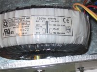
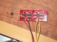
I get 25V readings coming from the Trafo into the PCB. Here is the trafo schematic. I wired it up per Brian GT's direction in previous post:
kestrel200,
Disconnect the trafo from the PCB with the diodes.
Power the trafo alone and measure the voltage.
Nothing?
Fuse Ok?
Or your trafo has some thermal protection and it's open (like a fuse when it blows), or you
ed the trafo. [/QUOTE]I get 25V readings coming from the Trafo into the PCB. Here is the trafo schematic. I wired it up per Brian GT's direction in previous post:
Attachments
Hi,
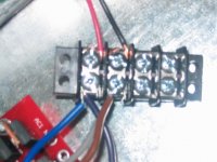
When taking measurement make sure the probe of your DMM does not make contact to the metal casing of the diodes. Your secondary connection to the bridge rectifier pcb looks ok.
I take it that your reading of 25V is AC. When you measure the V+ and PG+ what do you get? Make sure the DMM is set for DC.
Regards,
Chris
- Status
- Not open for further replies.
- Home
- Amplifiers
- Chip Amps
- Gainclone building thread based on BrianGT's boards