I cannot answer the question why the tube used this way sounds that transparent and indeed more transparent than used as ordinary triode plate and g2 connected. Actually I wanted a cheap alternative for the 300B and that's what I got. I can only say: Try it for yourself!
KeesB, thanks for your patient reply. I will try it some day to see/hear for myself! Thanks for your post.
Thanks, KeesB! I built mine using Tele E130L and driver 12SX7 cascode! I followed exactly your suggestion at Lenco Heaven to operates E130L @ Vb 275, Rk 1K5, Ik 20mA, Vk 32v. Sounding good with deep bass.
Nice to hear Zakk! Would you mind mailing me a picture of your build brakenhoffcj@gmail.com? It doesn't have to look as if it came right from the shop,
I received pictures of beautiful made chassis' and also just a wooden plank with everything on it, and an upside down cake tin. I like them all! I simply like the variety.
I received pictures of beautiful made chassis' and also just a wooden plank with everything on it, and an upside down cake tin. I like them all! I simply like the variety.
I meade the measurements of the g2 anode graphs and they look nice and linear. I thing a 2 or 2,2 K OPT would be best.
Thanks Steven. 6a3s (see post no 10) has shown that the un bypassed 390 ohm part of Rk heightens the output impedance with about 1400 ohms. Add this to the 2-2k2 you suggested and you have the 3k5 that I recommended. In general I find a somewhat higher impedance of the OT has a positive influence on the sound. There is less distortion albeit at a hardly noticeable lessening of the output power.
Kees, with 5 PL´s the lower Rk(680) would be around 136 ohm or I went for 120 ohm/7W ?
For the upper Rk(390) I took a 820 ohm/2W with a 470 ohm trimpot to equalize the current of each tube.
The OPT is 600/8, PY500A per channel with common sec output of 280V/1A 4,6ohm.
Now, 2 more questions:
Philippe
For the upper Rk(390) I took a 820 ohm/2W with a 470 ohm trimpot to equalize the current of each tube.
The OPT is 600/8, PY500A per channel with common sec output of 280V/1A 4,6ohm.
Now, 2 more questions:
- can you indicate the voltages on your schematic
- LC-filter
Philippe
How did you measure that result? Or is it simply an estimate (Guesstimate)?😊I estimate the output power to be about 3 wats. I have quite a few amps ( pp, se, both directly and indirectly heated) and this is one of the best sounding.
Decramer: Rcathode with 5 tubes would be 1k2: 5= 240 ohms; one third, 80 ohm is non decoupled. So you have 160 ohms. Diss. is approx. (at 50ma/519)
0,25 A x 40v = 10 w . I would use a 20w resistor there. The 80 ohms R diss. 5 w so take a 10w specimen.
Supply voltage is appox. 300v dc. I built I believe 5 amps like this and they all have slightly different supply voltages. That doesn't matter much as the tubes are thanks to the cathode resistors self- adjusting. And as it's SE the tubes don't have to be matched for equal currents. A friend of mine built one with 4 tubes
gave them a common Rk and has used it for several years without any problems.
I"ve estimated a current draw of appox. 50ma per tube. This is an estimate because of the current spread among those tubes which doesn't matter because the Rk provides dc feedback.
My friend's build with the 4 tubes used a crc suply with, if I remember well, 220 mu- 100 ohms - 470 mu. He used a bridge of UF 4007 rectifiers.
I hope this answers your questions if not let me know.
JHS: This is an estimate. I took 25% of the g2 dissipation (12,5 W).

I just wake up realizing I made a mistake. 50v across 1k = 50ma. ; 50v across 1k2 = 41ma. The reason for this that I made several amps using different cathode resistors. Sorry for the confusion this may have caused.
The higher Rk (1k2) makes for a g2 diss. of approx. 10w. It gives room for a somewhat higher Vb. Now you can go to Vb=320v without any problems.
When using Rk=1k as total resistance the upper resistor can be 330 ohms and the lower one 680 ohms. Now Vb should be about 300v.
The higher Rk (1k2) makes for a g2 diss. of approx. 10w. It gives room for a somewhat higher Vb. Now you can go to Vb=320v without any problems.
When using Rk=1k as total resistance the upper resistor can be 330 ohms and the lower one 680 ohms. Now Vb should be about 300v.
The only other place I'd ever seen the screen alone used as an anode is in a 6SJ7 mike preamp.
Circuit in the lower LH corner scanned from RDH4. I did use the first stage part in one project.
The grounded anode was meant to be a shield from external static & electromagnetic interference.
Very low current in this one, no danger of damaging the screen.
Circuit in the lower LH corner scanned from RDH4. I did use the first stage part in one project.
The grounded anode was meant to be a shield from external static & electromagnetic interference.
Very low current in this one, no danger of damaging the screen.
Attachments
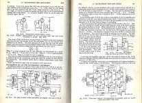
The BBC had a mini-mixer with 6AU6es, wired "plate" as shield and "screen" as anode. This gives a triode of good Mu and decent shielding without extra hardware. Obviously the current and power were far below maximum rating, being very small-signal.The only other place I'd ever seen the screen alone used as an anode is in a 6SJ7 mike preamp.
I didn't know these applications. Last year I saw a schematic of a pre-war Philips radio in which the if tube, an EF9, was used as phono driver by disconnecting the g2 decoupling c from ground and used as output capacitor driving the power tube. This was also new to me.The BBC had a mini-mixer with 6AU6es, wired "plate" as shield and "screen" as anode. This gives a triode of good Mu and decent shielding without extra hardware. Obviously the current and power were far below maximum rating, being very small-signal.
Then how did it start? As I had beautiful sounding prewar mesh anode power triodes I thought the wires that g2 are made of could be regarded as a mesh anode so lets try and see if we can get mesh anode-like results. Line deflection tubes were the obvious choice because of their relatively high g2 dissipation (and I had lots of those). Next question was, how far can we go? It appeared that at 15w dissipation some g2's were getting a little red, others did not.
So I decided to keep it safe and keep diss. at around 12w. I was very happy with the results, and the fact that J.Weiss marketed my idea (with an incredible price tag) was the reason to publish the circuit so it would become available for everyone.
The only other place I'd ever seen the screen alone used as an anode is in a 6SJ7 mike preamp.
Circuit in the lower LH corner scanned from RDH4. I did use the first stage part in one project.
The grounded anode was meant to be a shield from external static & electromagnetic interference.
Very low current in this one, no danger of damaging the screen.
This is also mentioned in some 6AU6 / EF94 datasheet out there, for the same reason (anode used as shield).
Kind regards, Tom
- Home
- Amplifiers
- Tubes / Valves
- G2 as anode PL519 power amplifier