Yours does seem to be a novel application of the idea.Line deflection tubes were the obvious choice because of their relatively high g2 dissipation (and I had lots of those).
Apparently so. Around 2004 or 2005 I looked around on internet but couldn't find something similar.
Kees, instead of a 5751, first I thought of using a ECC83 but now I have 12SX7 NOS. A better choice ?
Unfortunately the 12SX7 has a way too low gain (20) ; at the moment I'm using an ecc83 because as I said earlier you need quite a lot of gain as mug2g1 of the 519 is only 3.6. The dac I use doesn't put out a high voltage so the mu of the 5751 (70) was just a bit too low and with the 83 it was exactly right.

Hi all,
I found this thread while searching for "PL519 screen as anode", after reading Ale Moglia's post on building a preamp using a 4P1L tube with its g2+g3 used as anode. This intrigued me to build it and, indeed I quickly built one channel on a piece of plywood and tried it immediately. I was really astonished by the sound it produced, so, after having read a post of Kees in Ale's blog, I decided that I have to try this configuration with a power tube.
My question is whether g3 could be connected to g2, serving both as anode. This is the way they are connected in the example from RDH4 cited in post #33 from jhstewart9 and this is the way I have done with 4P1L.
Also, why not connect anode to ground or cathode and leave it floating?
Regards,
Evangelos
kenev,
In my Post # 4 of this thread, I said:
"2. On a different circuit . . .
I once built a 4-65A true tetrode amplifier. But . . .
The screen drove the primary of the output transformer.
The Screen maximum dissipation is 10 Watts.
The Plate Cap was connected directly to ground. No plate current.
The screen is built like a Bird Cage. But the plate hides the view of the screen.
The 4-65A is a very pretty tube."
Some really scratched their heads when they saw the 4-65A with a wire connected from the un-insulated plate cap to the top of the chassis (gnd).
In reality, I made the 4-65A operate as close to a triode as it can (closer than what some call "triode wired mode", which is when the screen is connected to the plate].
AKA Ale Moglia . . .
Your 4P1L used with g2 (and g3 also) as a "plate", will probably be similar.
You certainly can ground the plate and g3; or connect both g3 and plate to the cathode.
That will make the 4P1L operate as close to a Triode as it can (closer than what some call "triode wired" mode [screen connected to plate].
Do not leave any tube element disconnected (floating).
Just my opinion.
The result may vary, and may cause problems with the sound, clicks, or may cause some kind of tube failure or circuit failure.
Your Mileage May Vary.
Hint: A KT88 screen has an 8 Watt dissipation rating, an EL34 does too.
A 6550 only has 6 Watts maximum screen dissipation.
There may be a low power single ended amplifier with True Triode Operation mode of a KT88, EL34, or 4-65A in your future.
Have fun with these un-traditional operating modes.
Happy Listening!
Last edited:
Hello Evangelos,
I tries several things, connecting the anode to ground and also to a high negative voltage. I expected that a negative anode would repel electrons slipping through the g2 wires thereby pushing them back to g2 and that this would influence the sound (i used - 200v). However it didn't. I haven't tried connecting g3 with g2 so maybe that will do something. Also, grounding the anode made no difference. When you touch the anode of the 519 you can hear a very soft hum in the speakers so you can choose to leave as it is or ground it.
I tries several things, connecting the anode to ground and also to a high negative voltage. I expected that a negative anode would repel electrons slipping through the g2 wires thereby pushing them back to g2 and that this would influence the sound (i used - 200v). However it didn't. I haven't tried connecting g3 with g2 so maybe that will do something. Also, grounding the anode made no difference. When you touch the anode of the 519 you can hear a very soft hum in the speakers so you can choose to leave as it is or ground it.
Leaving an Anode to float, and then touching it, is like floating one end of a capacitor. Depending on what is at the other end of that "capacitor",
you might be giving a small charge to your finger.
If you touch the floating Anode, and you hear hum, then you are the antenna, and the Anode is acting like an extra grid.
Just my opinions.
you might be giving a small charge to your finger.
If you touch the floating Anode, and you hear hum, then you are the antenna, and the Anode is acting like an extra grid.
Just my opinions.
Last edited:
6A3sUMMER and Kees,
Thank you both for your replies.
I also thought that having the anode more negative would repel electrons escaping through the gaps of the screen/suppressor grids. I have to do some listening testings to see whether different connections of the anode might have a discernable difference.
Meanwhile, what I have in mind is drawing some curves with different anode connections to check its actual behavior (I have a uTracer curve tracer for this).
Regards,
Evangelos
Steve Bench used G1 as anode ages ago...
I guess other tubes can be used as well in case the grids 2 have similar dissipation rates.
I guess other tubes can be used as well in case the grids 2 have similar dissipation rates.
Lampie519,
You said:
Steve Bench used G1 as anode ages ago"
. . . What was he using for the control grid function?
Perhaps this is the case of using the Plate as a grid, and the grid as a plate.
That is documented.
And the document shows it to be a very impractical triode. Too many tradeoffs.
Or, was Steve Bench using G2 as an Anode?
That is far more practical than using G1 as an anode.
Just saying
Yes, many tradeoffs, just to show that there is hardly any new "invention" to be made with tubes that have not been done already in the past...
Somewhere in the early 2000's when I finished my g2 as anode 519 amplifier I was looking around the internet to see if anybody else had been doing this too but didn't find anything like that. That's when I stumbled upon Steve Bench's otl.
He developed an otl using g1 as anode and the anode as grid. Speaking about trade-off's: he used 10 5687's (= 20 triodes) to get an output of a few watts. An other version used I believe 8 or 10 6080's ( = 16-20 triodes in parallel). The driver needs to supply a high drive voltage as the gain of tubes used this way is the reverse of it's amplification factor. In case of the 5687 this is 1:17 and for the 6080's 1:2.
The driver needed 700 v to get the necessary drive. That meant a lot of material for a few watts.
I built the 6080 version some 20 yrs ago (mono).It's a direct coupled design (no output c ). The sound was beautiful, definitely. However the amount of material needed to build a stereo version and the amount of energy needed to get a few watts out kept me from doing so. Still it was a very interesting experiment. I don't know if his site is still active but if you're interested in unusual designs (like me) go there.
His site is archived. Some people have taken it onto their own page to keep the info available for us (kudos to them)
KeesB,
The trumpet player and singer, Chet Baker, did a song "Do It The Hard Way".
It reminds me of using the control grid as if it was a plate, and using the plate as if it was a grid.
Everybody has already climbed Mt. Everest, died trying, or stayed home.
If you want a real climbing challenge, then climb to the top of K2.
Just my opinions.
Because total current through a tetrode is pretty much given by G2 voltage it should be possible to install a switch between plate and screen; idle current and dissipation would change only a little bit, might even be feasable to throw that switch hot on the fly without a significant thump or voltage spike in the primary; or change in gain; can you hear the difference ... ?
I wanted to try to build a Zotl with this in mind as the current will be much lower on the screen grid this way. As there is no anode voltage present the voltage of the screen grid can be increased a lot.
Attachments

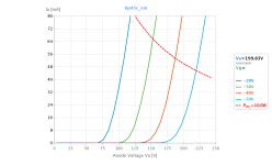
Last weekend, I put a Russian 6P45C on my curve tracer and got some curves with the tube in "screen mode" (g2 connected as anode, g3 tied to ground).
The curves are really impressive. Unfortunately my curve tracer (uTracer3+) cannot supply grid bias lower than -50V.
What was most impressive was the Ra and gm: ca. 550 Ω and 7 mA/V, respectively (I don't remember the exact figures, since I didn't write them down). Amplification factor is ca. 4.
Attached is an image of the traced curves. Quite linear as it seems.
Attachments
That's possible. Rk then becomes 1k3 ( I've built it myself ; one third of Rk is non- decoupled ) It doesn't have to be exactly 1k3 but don't go too low so as not to overload g2. Fortunately both the 519 and the 504 are strong tubes able to withstand some mishandling but you don't want to destroy them.
- Home
- Amplifiers
- Tubes / Valves
- G2 as anode PL519 power amplifier