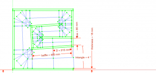
Too big (csa) too soon . Stay small longer and the midrange will fill in and the bottom excess will tighten down. All of this can be accomplished similarly by making the path longer too.and this is Jbell orginal dimmensions
View attachment 1131321
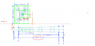
and 75 less dimmensions
View attachment 1131322
With a simple constant expansion double MTH or THAM type fold, break the horn path into 4 segments.
A 10ft (304.8cm or 120in) horn path let's me know there will be four 30in (76.2cm) segments. Add 3 pieces of wood thickness (0.75in or 1.905cm) and i know the external enclosure height will be 32.25in (81.915cm).
Depth of the enclosure depends on throat and mouth cross section areas (CSA).
Using a 15in driver (funny how no one says 38.1cm subwoofer INTERNATIONALLY) with a 2in (5.08cm) x 16in (40.64cm) throat and 10in (25.4cm) x 16in (40.64cm) mouth, we get an 8in (20.32cm) expansion.
Depth 1 = 2in (5.08cm).
Depth 2 = 10in (25.4cm).
Depth 3 = (Depth 1 + Depth 2) / 2.
Depth 4 = (Depth 1 + Depth 2) / 2.
[2in (5.08cm) + 10in (25.4cm)] / 2 = 6in (15.24cm).
Add 5 pieces of wood thickness 0.75in (1.905cm) to get the external depth total.
2in (5.08cm) + 10in (25.4cm) + 6in (15.24cm) + 6in (15.24cm) + 3.75in (9.525cm) = 27.75in (70.485cm).
External dimensions:
32.25in (81.915cm) High x 17.5in (44.45cm) Wide x 27.75in (70.485cm) Deep.
Internal volume:
30.75in x 16in x 24in = 11,808in3.
11,808in3 / 1,728in3 = 6.83ft3.
6.83ft3 x 28.317L = 193.5L.
I did this post on my phone while laying in bed!

To get the internal layout of the enclosure with a MTH left side exit, you use the 4 Depths at the bottom of the enclosure as such.
Front board, 10in (25.4cm), angled speaker board, 2in (5.08cm), vertical board, 6in (15.24cm), angled board, 6in (15.24cm), and rear board.
For the top of the enclosure, you would use:
Front board, 8in (20.32cm), angled speaker board, 4in (10.16cm), vertical board, 4in (10.16cm), angled board, 8in (20.32cm), and rear board.
However, for true constant expansion, the left 8in (20.32cm) could be 9in (22.86cm) and the right 8in (20.32cm) could be 7in (17.94cm).
Hey BP you are your phone are a dynamic DUO!!
See post #87 that's the original folding from the stadium horn, so I clearly see that the path length is less there than on your multifold design.
I was going to simulate the PRV 15SW2000 on the stadium horn to see what I can get.
If the layout is not angled so too have a horn expansion but just a TL , how that change the response?? I mean it's crazy how an expanding tunnel have an amplifier effect on the soundwaves than just a fixed volume tunnel.
Thanks for your help BP and it is a greater feat coming from your cell.
I don't know how to make the hornresp data in to a real box.
If you use the freecad model, it's straight forward to tweak the box and it will generate the hornresp input automatically for you. But anticipating to you, this type of box you can tweak only a few parameter as indicated below.
- Baffle size
- Drive position
- S1 height
- Flare angle
- wood thickness
The main dimension to reduce Horn length is the baffle size but you can't go under the the minimum size you need to mount the driver on it, the flare ratio and S1 height also helps a little, but, at the end you will discover that you reach a limit with this design and it may not be possible to target 42Hz. In this case you may discover that you need to move to a different design option with different layout like TH-SS or TH-DF.
For 42Hz the 1/4 Wave Length is:
sound speed / frequency target / 4 = 343 m/s / 42Hz / 4 = 2,04m this is your target for total horn length.
You can target to any frequency once you keeping your eye on the Eg and Diaphragm Displacement.
Attachments

i put my eye on the stadium horns cause is less folding so easier to build
just wanted to see if using another driver and maybe making it smaller will give me better results.
but its an effing balancing act as Brian Steele once said, you move something and everything else move
and then you hit a brickwall cause you cant make something smaller cause the driver do not not fit anymore in the baffle or the cabinet is effin large
arrggg... this is not easy 🙁
They are the same MTH fold with optional mouth exits. Tom Danley provides a 3rd option side mouth exit with his TH's.and this is the Stadium horn folding besides the BP1 folding
View attachment 1131524
1st of all, you are building a parabolic enclosure so your L12, L23, & L34 should be Par and not Con.
They have similar dimension except the FurySub has wasted space at L12 (S1 to S2).
My TH does not use corner braces.


My TH does not use corner braces.
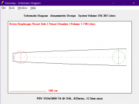
I fixed my hornresp entry for your TH for the 15SW2000 however if all hornresp boxes are the same i got a little discrepancy on on the system volume
yours on LEFT
see the pic below


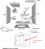
What was the function of the compression rectangle opening he added ( rectangle window )
i read that the cone to have compression and protect the driver , looks like that saved the 3015LF's from being destroyed on his 6 fury subs cabinets that were abused 6 days a week on the club.
i wish i can experiment with that making a movable metal sliding door type with sheet metal , kind of barn door but more like the camera IRIS thing so to take reading at different opening sizes and shapes. rectangle, circle, keystone, and multi.
just in the name of science to see what results you get, however it needs to be at lower levels i think so the metal sheet so not bend.
but if it works at low level maybe that will tell us how it will be at higher SPL's.
is there software to simulate how forced air trough a smaller gap load or unload a driver cone ?
adding that in front of the cone, will "protect" the cone at some extent ?
yours on LEFT
see the pic below
What was the function of the compression rectangle opening he added ( rectangle window )
i read that the cone to have compression and protect the driver , looks like that saved the 3015LF's from being destroyed on his 6 fury subs cabinets that were abused 6 days a week on the club.
i wish i can experiment with that making a movable metal sliding door type with sheet metal , kind of barn door but more like the camera IRIS thing so to take reading at different opening sizes and shapes. rectangle, circle, keystone, and multi.
just in the name of science to see what results you get, however it needs to be at lower levels i think so the metal sheet so not bend.
but if it works at low level maybe that will tell us how it will be at higher SPL's.
is there software to simulate how forced air trough a smaller gap load or unload a driver cone ?
adding that in front of the cone, will "protect" the cone at some extent ?
Attachments
Last edited:
I account for the speaker plate hole volume with
ATC = Sd = 908cm2.
Vtc = 908cm2 x 0.75in (1.905cm) = 1729.74cc.
ATC = Sd = 908cm2.
Vtc = 908cm2 x 0.75in (1.905cm) = 1729.74cc.
- Home
- Loudspeakers
- Subwoofers
- Furysub, Apache H15, or Jbell 2' cube