Krell experimented with transimpedance main amps, transferring just current from the preamp through the interlink ending in a zero ohm virtual input.
Although a promising apoach, it deviated too much from the standards in the industry and was abandoned as far as I know.
Now with MC Carts you see transimpedance coming back in several phono preamps.
I like the clarity of your presentations Hans. English is a second language for me... unfortunately it is also my first...
This is unlike a good friend of mine, a Dr. Zdenek Kucerovsky, a physicist of Czechoslovakian decent, being fluent in his own language, English, Russian, and German. This was so he could read physics papers by authors in their original language, often finding them badly translated. My niece, who was in Electrical Engineering at the time, once complained to him that she couldn't comprehend an instructor she had of Russian decent. Having familiarity with all kinds of students and their usual complaints he responded with "then learn Russian..." in his characteristically monotonic and unsympathetic voice.
The Krell approach using transimpedance is promising from a dielectric perspective, this for the same reasons as transimpedance termination for MC cartridges. In my past life... before retirement... though after my reincarnation from a previous life as a karma… I was often contracted by members of the Applied Electrostatic Research Group to create variant measurement apparatus and commercial devices for electrostatic applications, as well as conducting measurements in the field. So there is familiarity with electric fields, electron flow, electron accumulation, etc., that often involves dielectric materials. Coincidentally the dielectric of choice is often teflon.
In electrostatics research there are two basic forms of measurement, voltage and current, whereupon careful consideration is given to the extreme impedances that can exist, those whereupon capacitance becomes extremely important to reflect upon. Either capacitance is used to accumulate charge in a transimpedance network or driven out of impacting the measurements using a driven shield. These are shown below:

In both cases the idea is to maintain equal potentials between the high impedance input signal and the surrounding shield, this translates as equivalent of minimalist capacitance between the signal to the shield in both cases. This minimizes charge migration and loss into the dielectric material. Charge migration into the shield caused by increasing the effective capacitance also limits frequency response. As an aside, the tri-axial cable method was used in conjunction with other electronics designed with minimalist bias currents of < 0.5 femto-amps adequate to measure voltage signals internal of the brain of rodents. Driving the shield was also necessary to increase bandwidth. By the way, I hated anything to do with animal research and tried to avoid it.
It seems that the cables used in audio are only either co-axial or balanced. From an electrostatics perspective voltage measurement is often a non-starter in absence of some mechanism of capacitance reduction. In audio, if it can be relied upon that cables only present a pure capacitance then things seem could be more predictable. However, as you seem to suggest, cabling is extraordinarily variant of sonics IMO. This notwithstanding, even teflon takes on charge, that in the extremes of measurement sensitivities, the bending of a teflon cable can overwhelm the measurements by the turboelectric effect. This also questions the mechanical integrity of electronic devices of impacting sonics, a condition that I suspect many companies do take into account. This says nothing yet about circuit board dielectric materials in conjunction with creating capacitances using ground planes.
The case of the balanced cable depicted in the above is interesting to consider, in that its configuration seems can be likened to an unshielded twisted pair as far as dielectrics are concerned. The effects of the shield appear neutralized as the net voltage of the twisted differential pair to the ground shield is zero, hence does not appear would impact the signal significantly. As dielectric influences seem can be diminished by such balanced configuration it is perhaps the reason that increased resistance can be added in series from the source with positive benefit, perhaps no differently from driving an unshielded twisted pair.

Again, interesting considerations, but to comment with respect to your images:
The two upper images only send one line, where you always need two lines to transfer a signal, seemingly an open door, but the analog gnd on the the sending side is not the same as the analog gnd on the receiving side and that's why the shield is used as a way to connect both, but there you will have the full cable capacitance.
That may, as you indicate, be the reason to use a lower R0 from the sender as with a Diff connection.
But apart from capacitance there is also the need for shielding against EMI.
So technically, the best option IMO is your #3 image, where the shield is connected to the senders case which is connected to PE.
In that way the shield acts as an extension of the metal housing to protect against EMI.
Better is not to connect this shield to the receiving case and even worse is to connect it to the receivers analog gnd.
This type of connection is called OEO or One End Only and that's how I have connected all my gear.
https://www.linearaudio.net/index.php/pin-1-revisited-adding-oeo-accepted-rule
But as mentioned earlier, there are also people like Markw4 having the fixed conviction that SE always sounds better.
So technically the best option may sometimes not be the best audio option 🤣
Hans
Hmmm, that is very interesting.....
Personally, I never heard difference between cables providing they are of the same configuration and decently executed. Since long time I use only pro "microphone" cables (like picture 3 above: twisted pair -filler - shield - outer jacket) and grounded on both sides. The shield becomes chassis (or extension of the chassis), all chassis have very similar ground potential then. Never had hum - buzz issues with that. Sometimes i had issue, but cause was always elsewhere....
It also opens the question why pro audio people normally don't waste money on cables (but never give up fully balanced XLR or TRS) and spend fortune on speakers or mixers for instance... I think it is because that part works.
There are very nice (and old) articles from Stephen Macatee and Bill Whitlock on this, somewhere on forum I left pdf's but not sure where, here are new copies in case you did not see those.
Only issue left IMHO is ground loops, tackled by bundling signal and power cables to reduce loop area, using batteries at sources or reducing number of components.....
Attachments
Again, interesting considerations, but to comment with respect to your images:
The two upper images only send one line, where you always need two lines to transfer a signal, seemingly an open door, but the analog gnd on the the sending side is not the same as the analog gnd on the receiving side and that's why the shield is used as a way to connect both, but there you will have the full cable capacitance.
That may, as you indicate, be the reason to use a lower R0 from the sender as with a Diff connection.
But apart from capacitance there is also the need for shielding against EMI.
So technically, the best option IMO is your #3 image, where the shield is connected to the senders case which is connected to PE.
In that way the shield acts as an extension of the metal housing to protect against EMI.
Better is not to connect this shield to the receiving case and even worse is to connect it to the receivers analog gnd.
This type of connection is called OEO or One End Only and that's how I have connected all my gear.
https://www.linearaudio.net/index.php/pin-1-revisited-adding-oeo-accepted-rule
The images were mostly very carelessly drawn... leaving out the obvious to me (and seemingly to you as well). I should be more careful given that others are likely reading this also.
An excellent reference in my possession seemingly forever, being published about 40 years ago now (and coincidentally beside me when I was writing this), is "Grounding and Shielding Techniques in Instrumentation" by Ralph Morrison. This goes into significant detail for the lay person on the topics stated in its title and to your point.
https://www.linearaudio.net/index.php/pin-1-revisited-adding-oeo-accepted-rule
I looked up your link above and happened to look at the diagram in the upper right corner. It shows 50pF between the signal conductors with 3.3nF from each conductor to the shield. Being series connected this suggests 1.65nF across the signal conductors in parallel with the 50pF, suggesting that the shield is dominating the capacitance across the differentials, not the 50pF. Does this convey that because the signals are differential that the effective capacitance to the shield is neutralized to effectively 50pF across the differentials? This seems supporting my contention that adding resistance in series in a balanced configuration isn't nearly as serious as using a coax that wouldn't neutralize its possible 3.3nF shield capacitance.
But as mentioned earlier, there are also people like Markw4 having the fixed conviction that SE always sounds better.
So technically the best option may sometimes not be the best audio option 🤣
Hans
I mostly only restarted using differential lines recently, being of an opinion that SE can have significant advantages over differentials. Just as cables have sonic implications so does any amplification device. In the case of balanced it is often necessary to include further amplification devices to send and receive differentials that in turn are themselves highly suspect of imposing sonic character.
SE and DS both have 2 lines referenced to each other, as being the signal passed on. In the case of SE the ground is being shared, that under circumstances being substantively unknown as to the means the ground reference can being corrupted, it is advantageous to avoid using ground to carry signal. It seems that one of the highest levels of uncertainty in causing sonic corruption is in the interconnection between independently line powered devices. Notwithstanding that such devices have galvanic isolation there can exist considerable capacitive AC coupling within transformer windings, coupling that can loop high frequencies around via the power cords causing voltage to be developed between a driver and receiver (seemingly as Vcm in the diagram in your link)
Ground loops seems a primary concern. A professional studio, or some venue that is highly reliant upon punctuality and functionality can't afford spending hours, perhaps even minutes, for a technician to figure out why something is humming like a banshee (to be clear... I have nothing against banshee's as a group). XLR's exist of solid mechanical integrity as well, so there is no mystery to me at the moment that I can think of.Only issue left IMHO is ground loops, tackled by bundling signal and power cables to reduce loop area, using batteries at sources or reducing number of components.....
Perhaps in some agreement with Markw4 (though perhaps for differing reasons), there seems no benefit to using DS inside a device whereupon ground signal integrity is controllable using SE. Hence DS in and out with SE internal seems to cover all the bases seemingly necessary as a direction most simplistic.
In fact the the two 3.3nF caps are in parallel to both output resistances Rs1 and Rs2 and there’s only the 50pF is across the lines.Being series connected this suggests 1.65nF across the signal conductors in parallel with the 50pF, suggesting that the shield is dominating the capacitance across the differentials, not the 50pF. That is not the case.
You can also find this on page 13’s lower end of the Whitlock ducument linked to in #303 that Drbulj gave.
But that’s only true when the shield is connected to the sending side.
Whith the shield connected to the receiving side the two 3.3nF caps are in series with Rs1 and Rs2 to gnd, therby acting as low pas filters.
That’s exactly what OEO is about.
Giving full isolation for gnd noise and a very low capacity between the signal lines.
Hans
I don't see it Hans.
Notwithstanding the existence of Rs1 and Rs2 there are 3 capacitances with 3 nodes connected in a loop. The two 3.3nF capacitances become nullified by the close coupling of the two differential lines presenting a zero net field to the shield if differentials signals are equal and opposed, whereupon the effective capacitance to the shield doesn't appear existing to the differentials.
Imagine the differentials as intimately coupled, then there is no net field to the shield.
What is interesting now that I am thinking about it... is that any imbalances seems can drastically change the capacitance effect because of the large difference between the 50pF and the 3.9nF values. Seems a case to maintain exceptional balance.
Last edited:
I have tried in the image below to go in 4 steps to the point where it becomes obvious that the the two 3.3nF caps are in parallel to Rs1 and Rs2.I don't see it Hans.
In the second image I have divided the voltage source in two independent sources.
Then without changing anything, the screen sides of the two 3.3nF caps are shifted to another point of the sender´s chassis.
Since each voltage source has an internal resistance of zero Ohm, in the fourth image the two 3.3nF caps are placed in parallel to RS1 and RS2.
Hans
I am too Hans... though the end model itself looks plausible. The difficulty is in modelling the implications of the fields. I can't think of a way to get to the end model.
In the diagrams you have, when the signals are true differential the 50pF can be split into two 100pF capacitors with the center connected to a virtual ground. This means that the networks can be examined from a SE perspective with a 100pF terminated into ground, making it even more difficult to get to visualize an electrical equivalent model. It seems that electric fields must be included in the modelling. No clue how...
In the diagrams you have, when the signals are true differential the 50pF can be split into two 100pF capacitors with the center connected to a virtual ground. This means that the networks can be examined from a SE perspective with a 100pF terminated into ground, making it even more difficult to get to visualize an electrical equivalent model. It seems that electric fields must be included in the modelling. No clue how...
Last edited:
Please pardon me for butting in but your conversation is great. Many standalone DAC/ADC's, measuring best in reviews and offering SE and balanced diferential options, measure better on the balanced differential analog I/O than on the SE. Why not stay diffential balanced unless strongly compelled otherwise?. It just seems safer these days with all the highly distributed switching power and high speed digital computing. Unless you are on a tight budget of course.there seems no benefit to using DS inside a device whereupon ground signal integrity is controllable using SE.
It's as though Vcm is the third important signal in the differential pair of siggnals. Vcm should be kept as pristine as possible for both driver and reciever whether the transmission is isolated or not.SE and DS both have 2 lines referenced to each other, as being the signal passed on. In the case of SE the ground is being shared, that under circumstances being substantively unknown as to the means the ground reference can being corrupted, it is advantageous to avoid using ground to carry signal. It seems that one of the highest levels of uncertainty in causing sonic corruption is in the interconnection between independently line powered devices. Notwithstanding that such devices have galvanic isolation there can exist considerable capacitive AC coupling within transformer windings, coupling that can loop high frequencies around via the power cords causing voltage to be developed between a driver and receiver (seemingly as Vcm in the diagram in your link)
Ground loops seems a primary concern. A professional studio, or some venue that is highly reliant upon punctuality and functionality can't afford spending hours, perhaps even minutes, for a technician to figure out why something is humming like a banshee (to be clear... I have nothing against banshee's as a group). XLR's exist of solid mechanical integrity as well, so there is no mystery to me at the moment that I can think of.
Perhaps in some agreement with Markw4 (though perhaps for differing reasons), there seems no benefit to using DS inside a device whereupon ground signal integrity is controllable using SE. Hence DS in and out with SE internal seems to cover all the bases seemingly necessary as a direction most simplistic.
my personal rant: too bad about all the foregone "free" high frequency common mode rejection performance not being achieved due to less than optimal board trace and component layouts. The mirrored symmetry fad seems ubiquitous among high end audio though does not seem optimal. It seems easy to imagine how much better a paralleld copy approach could perform with regard to achieving as close as possible to perfectly uniform noise field exposure, by both positive and negative circuits .... and yet all the mirrored symmetry layouts out there...
The answer to the question was simply found by simulating the circuit in LTSpice.I am too Hans... though the end model itself looks plausible. The difficulty is in modelling the implications of the fields. I can't think of a way to get to the end model.
And Indeed the driver's series resistances and the cable capacitance from signal-wire to cable-shield forms a low pas filter in all cases.
Bill was simply wrong in his assumption that the caps became in parallel to the output resistances, good that you questioned this.
What was confirmed in the sim was that CMRR will not be not affected by Vcm when connecting the cable-shield to the drivers side.
However only small value differences between both output-resistances and/or between both cable capacitances are causing large effects on CMRR, depending on the -3dB point of the low pass filter function.
In Bill's case he used 3.3nF for a very long 20ft cable.
My interlinks are ca. 20pF/ft, that would mean a ridiculous ca. 50 meter cable to get 3.3nF !
But obviously it pays somehow to use low capacitance cables when trying to achieve high CMRR over the frequency band of interest.
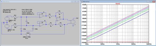
In the example below I have used 2*150pF instead of 2*3.3nF, used a Receiver with a very high input impedance and CMRR, and varied RS3 from 100R to 105R in five 1R steps.
The graph shows the CMRR with these five RS3 variations.
Hans
Attachments
Hello all,
Im back from holidays and found our house being reclaimed by nature, looks like we were out for couple of years, not weeks... So lawn mover, saw and broom in action, in addition my kid restarted school this week, and all parents are not doing good with their health. Many things to take care off before spending hobby time.
In the meantime I was reading very interesting talks on this thread, from CFA video amps to cables and the ultimate answer of universe, It will take me some time just to like everything 🙂
Still I managed to spent few hours to check what was wrong with my measurements. On holidays I read REW RTI window instructions more carefully, and as usual, Hans Polak was right 🙂
I soldered SSM2017 in the box again, in normal voltage mode. following is exact diagram and picture of the box:


Than I set REW RTI window as here, spectrum not RTA:

The input signal is 1V reduced to 0.35mV via 47k and 33R resistors. RG is 33 Ohm giving little bit less of 50db gain. Measured Vo is 103mV. all fits!
This is the result of it:

Whomever is kind enough to check and point out if there is still mistake in set up, I appreciate very much!
Dražen
Im back from holidays and found our house being reclaimed by nature, looks like we were out for couple of years, not weeks... So lawn mover, saw and broom in action, in addition my kid restarted school this week, and all parents are not doing good with their health. Many things to take care off before spending hobby time.
In the meantime I was reading very interesting talks on this thread, from CFA video amps to cables and the ultimate answer of universe, It will take me some time just to like everything 🙂
Still I managed to spent few hours to check what was wrong with my measurements. On holidays I read REW RTI window instructions more carefully, and as usual, Hans Polak was right 🙂
@Drbulj,
First the spectra that are shown.
I think I can see why your noise is increasing with frequency.
It’s because what is dispayed are parts of an octave, 1/48 to be precise, and not fixed frequency bins as the usual way to display.
As an example, an octave at 50 Hz goes to 100Hz and at 5Khz to 10Khz.
Suppose you have 1nV/rtHz, then from 50Hz to 100Hz you have sqrt(50)*1nV = 7.1nV but from 5Khz to 10Khz you will see 71nV or 20dB more noise.
So, when working with octaves or parts of octaves, the noise spectrum will go up with 10dB/decade.
Switch it off and you will see the flat spectrum that is more meaningful.
Hans
I soldered SSM2017 in the box again, in normal voltage mode. following is exact diagram and picture of the box:
Than I set REW RTI window as here, spectrum not RTA:
The input signal is 1V reduced to 0.35mV via 47k and 33R resistors. RG is 33 Ohm giving little bit less of 50db gain. Measured Vo is 103mV. all fits!
This is the result of it:
Whomever is kind enough to check and point out if there is still mistake in set up, I appreciate very much!
Dražen
And few more screen shots that might be interesting to look, not related to amplifier itself but to general practice::
This is window showing my test set up with no signal; upper trace with power, lower switched off (just system noise picked up)

Also this is probably interesting; one trace with amplifier powered (take it as comparison between 2, this time it was set for 60db gain, so not related to other charts) . Difference between traces is only that on noisy one (blue) lid of the box was removed, on the other it was closed (green). Unbelievable how much 50Hz is hanging in the air to be picked up:

This is window showing my test set up with no signal; upper trace with power, lower switched off (just system noise picked up)
Also this is probably interesting; one trace with amplifier powered (take it as comparison between 2, this time it was set for 60db gain, so not related to other charts) . Difference between traces is only that on noisy one (blue) lid of the box was removed, on the other it was closed (green). Unbelievable how much 50Hz is hanging in the air to be picked up:
The answer to the question was simply found by simulating the circuit in LTSpice.
And Indeed the driver's series resistances and the cable capacitance from signal-wire to cable-shield forms a low pas filter in all cases.
Bill was simply wrong in his assumption that the caps became in parallel to the output resistances, good that you questioned this.
Makes sense now Hans. The only thing questionable is that the capacitance effects are not completely separable in reality, rather fields are interplaying within the common dielectrics of the cable capacitances, suggesting that there can be less dielectric consequences sonically than the absolute values might suggest. Okay... now my head is starting to hurt... where's my mommy?...
The values of capacitances were suspect to me as well... and keeping capacitances low in general seems a good idea notwithstanding the quality of the dielectric being suspect.
I’m not fit in REW, that’s producing an overwhelming amount of data, but the specified 65dB S/N looks pretty good.Whomever is kind enough to check and point out if there is still mistake in set up, I appreciate very much!
This corresponds nicely with the 64.4dB that I predicted in #238.
You could probably flatten the noise spectrum by averaging over an amount of spectra.
Hans
Thanks Hans,
Yes, your calculation was spot on, as it is the chip specification. I wait for more comments on measurement set up, but it looks good for now.
One short comment for your discussion with Hierfi about cables and termination, in diagram you see I added 75R termination on both ground and signal. When fully balanced +and - signals are not available I do that to match impedance at least, it helps CMMR at receiving end.
Cheers,
Dražen
Yes, that's perfectly correct to turn SE into Balanced.One short comment for your discussion with Hierfi about cables and termination, in diagram you see I added 75R termination on both ground and signal. When fully balanced +and - signals are not available I do that to match impedance at least, it helps CMMR at receiving end.
Hans
Hi Dražen,
However this might work are you planning to ultimately operate the network below running off 9 volt batteries, this with XLR's in and out as depicted?

I suspect the devices take about 5mA each, hence 10mA in stereo. A good alkaline battery seems likely would last about 50 or so hours at 10mA, meaning replacing the batteries every 50 hours. In my case this would mean replacing the batteries after failing to observe that my stylus was playing the inner groove for the past couple days.
I also used batteries up until recently... despite having developed a strong dislike for them because of their nuisance factor. Basically having to always monitor their status and replacing them. Though in my case the battery life was expected in the 500 hour region. As an aside, I designed a network that monitored the R/L channels and continuously activated a reset of a 15 minute timeout delay that disconnected the batteries. In other words if the signals were below the reset trigger levels in playing inner grooves for 15 minutes the relays would disconnect power. Meaning I could play an inner groove over my vacation without worrying about discharging the batteries.
The reason batteries were abandoned was because of the SSM2019, whereupon there also seems no need of a separate head amp as before, hence no added XLR cables or their terminations to be concerned with. The shunt supplies used currently for the SSM2019 appear below as likely overkill, being a minor variant of what appears somewhere on the diyAudio forum. I added some low noise green leds in the reference lines to see if the power supply became inadvertently shorted.

However this might work are you planning to ultimately operate the network below running off 9 volt batteries, this with XLR's in and out as depicted?
I suspect the devices take about 5mA each, hence 10mA in stereo. A good alkaline battery seems likely would last about 50 or so hours at 10mA, meaning replacing the batteries every 50 hours. In my case this would mean replacing the batteries after failing to observe that my stylus was playing the inner groove for the past couple days.
I also used batteries up until recently... despite having developed a strong dislike for them because of their nuisance factor. Basically having to always monitor their status and replacing them. Though in my case the battery life was expected in the 500 hour region. As an aside, I designed a network that monitored the R/L channels and continuously activated a reset of a 15 minute timeout delay that disconnected the batteries. In other words if the signals were below the reset trigger levels in playing inner grooves for 15 minutes the relays would disconnect power. Meaning I could play an inner groove over my vacation without worrying about discharging the batteries.
The reason batteries were abandoned was because of the SSM2019, whereupon there also seems no need of a separate head amp as before, hence no added XLR cables or their terminations to be concerned with. The shunt supplies used currently for the SSM2019 appear below as likely overkill, being a minor variant of what appears somewhere on the diyAudio forum. I added some low noise green leds in the reference lines to see if the power supply became inadvertently shorted.
- Home
- Source & Line
- Analogue Source
- Fully balanced MC phono preamplifier thoughts