The data sheets indicates good noise performance at 1KHz. Do you know of any data of on behaviour lower down in frequency... graphs perhaps? Has anyone used them for phono applications?
@Hierfi, I presume you're referring to THAT devices?
Not the last word in matched arrays or MC head amps, but I used THAT 340 to built a common-base current-mirror version of the Leach head-amp. Works great, clear articulate sound, very low noise even at 33dB gain.
I don't have the bench/test equipment to be measuring performance or matching devices, so THAT is why I chose the 340, a no-brainer for me.

Are you referring to the current mirror version in the following?
https://leachlegacy.ece.gatech.edu/headamp/
https://leachlegacy.ece.gatech.edu/headamp/
Yes, that's the one. I built the original Audio Mag version in the mid '80s, decided to upgrade a few years ago.
Someone mentioned the INA103 earlier in this thread.
https://www.ti.com/lit/ds/symlink/i...62374&ref_url=https%3A%2F%2Fwww.google.com%2F
Like many other devices it too has a 1nV/√Hz specification. Though it should be noted that unlike the SSM2017(19)'s the INA103 has balanced +/- GainDrive feedback pins that can be used to drive an RIAA stage differentially in a fully balanced phono network. However this device could be more problematic to potentially damage the coils if the coils are connected across the inverting input terminals in the current mode, as the inverting terminals appear low impedance bi-directionally, meaning capable of sourcing/sinking significant current into the coils if the +ve input terminals are separated significantly.
In contrast the SSM2017(19)'s has each half sourced by a constant current, hence differential currents don't exceed the magnitude of the sinking current sources (and corrective feedback currents). This is seemingly much safer, as the device being used currently in current mode.
@Hans Polak ,
Not now, thing is that I'm on holidays far south in Adriatic, fishing and boating with family. I'll be back in about 2 weeks, than I can check it in workshop, I'm also eagar to see what it will show.
Low frequency spectrum shoved excellent performance with ssm2017, if I got it right my mistake in measurement only collected more noise energy as frequency raises, but low end is represented all right... Looking forward,
Cheers,
Dražen
Hi,
the INA103 seems to be the anchestor of those very lownoise INAs from TI.
I used it in my thesis -a modular preamp.
Later the INA163_166 and others appeared.
The above mentioned additional two pins of the INA103 are unique in this family.
TI doesn´t suggest to use them as balanced output as it may spoil the CMRR.
Rather they intened them to synthezise a signal to drive a triaxial input cable .... a rather non-audio application.
So far I never exprienced a dangerous situation for attached pickups, but I know that it happened once that a pickup was grilled when one of the supply lines failed (it must have been a unbalanced connection to the pickup, because in balanced mode both inputs generate a same input offset).
If one wants to go fully balanced I think that THATCorp offers an almost ideal chip-combo THAT1570/5571, which features a fully balanced input stage and a software controlled gain-setting feedback stage.
If I weren´t a complete software Dodo, I´d for long had designed a Phono-Pre by now.
jauu
Calvin
Hi,Why are you applying a mic calibration file?
I'm applying calibration file made for soundcard, it shows as mic file but it's just card. I'm not sure if it is possible with REW to apply separate cal. files for soundcard only, than add mic when needed. Still learning this 🙄.
Cheers,
Dražen
What is that calibration file supposed to do? Calibration files are typically needed for notches or similar. The strange looking noise floor may be from the calibration file so maybe you should try without it.
There is option to calibrate soundcard. I read instructions and if I got it right software will deduct soundcard noise from measurements ti get closer to D.U.T. performance?
An often overlooked advantage of the INA 103 over similar parts from other manufacturers is the +/-24 V supply rating, allowing a higher overload margin. In principle, a phono preamp using the INA 103 and OPA 2604 could be run off 22 V rails offering a useful increase in overload margin relative to 15 V rails.Someone mentioned the INA103 earlier in this thread.
https://www.ti.com/lit/ds/symlink/ina103.pdf?ts=1725009762374&ref_url=https%3A%2F%2Fwww.google.com%2F
Like many other devices it too has a 1nV/√Hz specification. Though it should be noted that unlike the SSM2017(19)'s the INA103 has balanced +/- GainDrive feedback pins that can be used to drive an RIAA stage differentially in a fully balanced phono network. However this device could be more problematic to potentially damage the coils if the coils are connected across the inverting input terminals in the current mode, as the inverting terminals appear low impedance bi-directionally, meaning capable of sourcing/sinking significant current into the coils if the +ve input terminals are separated significantly.
In contrast the SSM2017(19)'s has each half sourced by a constant current, hence differential currents don't exceed the magnitude of the sinking current sources (and corrective feedback currents). This is seemingly much safer, as the device being used currently in current mode.
I can envisage the following topology for, say, an AT OC 9: balanced input transformer (gain 10-15) —> INA 103 (gain 100) on secondary for balanced to single ended —> Opa2604 for eq and high pass (not the lowest noise, but adequate). Galvanic Isolation of the cartridge and good CMRR are well worth the expense of a good input transformer, AFAIAC.
Anyone know of a lower noise Op amp than the 2604 that can run on 24V rails? If so, please advise.
Also, if you have 2604s DIPs that you don’t need please contact me. I hope the moderators will not mind🙏.
Last edited:
Hi,
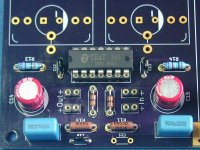
You mean something like this? 😎

I have built with +-15V supplies since then wo. any issues regarding overload ... but it wouldn´t harm running it on 24V either.
The nominal output voltage I specced to be 300mVrms for input signals from 150µV@5cm/s up to a couple of mVs ... hence low-out MCs up to high-out MMs could be run.
Its just that below ~150µV the noise floor slowly becomes audible ... still better than many commercial Phono-Pres though.
I never used the circuit with an input transformer, as the INA is so low-noise that it doesn´t need it for this reason ... but it has been done, since some Highenders want it so, as it´s their firm belief that transformers are generally ´better sounding´ input devices. 🙄
Instead one can make full useage of the high flexibility of this circuit (balanced/unbalanced In -- highly versatile gain, almost any pickup on the market could be served -- effective DC-servo, resp. Subsonic filter at an early stage -- etc.).
Due to the high gain of the first stage, the second active stage´s contribution to the overall noise figure is small.
Since IC2 and IC3 see source impedances of >2.8k up to 100k JFET-Input OPAs with reasonable low en of <10nV/vHz@1khz and typical vanishingly low in are suitable.
Of course did this circuit evolve over the decades ..... it just ended its 3rd decade of life (see Oct. 1993!) and began it´s 4th ... but it were smaller refinements, rather a evolution of a generally very capable topology.
The last major update I did was a complete new PCB-layout with a refined and beefy grounding and supplies scheme.
Don´t underestimate the layout and associated power supply parts. 😉
jauu
Calvin
You mean something like this? 😎
I have built with +-15V supplies since then wo. any issues regarding overload ... but it wouldn´t harm running it on 24V either.
The nominal output voltage I specced to be 300mVrms for input signals from 150µV@5cm/s up to a couple of mVs ... hence low-out MCs up to high-out MMs could be run.
Its just that below ~150µV the noise floor slowly becomes audible ... still better than many commercial Phono-Pres though.
I never used the circuit with an input transformer, as the INA is so low-noise that it doesn´t need it for this reason ... but it has been done, since some Highenders want it so, as it´s their firm belief that transformers are generally ´better sounding´ input devices. 🙄
Instead one can make full useage of the high flexibility of this circuit (balanced/unbalanced In -- highly versatile gain, almost any pickup on the market could be served -- effective DC-servo, resp. Subsonic filter at an early stage -- etc.).
Due to the high gain of the first stage, the second active stage´s contribution to the overall noise figure is small.
Since IC2 and IC3 see source impedances of >2.8k up to 100k JFET-Input OPAs with reasonable low en of <10nV/vHz@1khz and typical vanishingly low in are suitable.
Of course did this circuit evolve over the decades ..... it just ended its 3rd decade of life (see Oct. 1993!) and began it´s 4th ... but it were smaller refinements, rather a evolution of a generally very capable topology.
The last major update I did was a complete new PCB-layout with a refined and beefy grounding and supplies scheme.
Don´t underestimate the layout and associated power supply parts. 😉
jauu
Calvin
Hi,
Second gain stage will be after HF cut, so absolutely no worries about overload and no need for opa2604 if you reduce VPS for it. First INA stage can benefit from high PS voltage in order to maximize gain. I used +-18V and gain 60db without clipping
Second gain stage will be after HF cut, so absolutely no worries about overload and no need for opa2604 if you reduce VPS for it. First INA stage can benefit from high PS voltage in order to maximize gain. I used +-18V and gain 60db without clipping
An often overlooked advantage of the INA 103 over similar parts from other manufacturers is the +/-24 V supply rating, allowing a higher overload margin. In principle, a phono preamp using the INA 103 and OPA 2604 could be run off 22 V rails offering a useful increase in overload margin relative to 15 V rails.
Galvanic Isolation of the cartridge and good CMRR are well worth the expense of a good input transformer, AFAIAC.
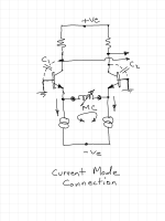
The coils in a MC cartridge are already galvanically isolated, that as a result can be floated as replacing the gain setting resistors in SSM2017(9) (or other devices). With the +/- inputs returned to ground the ends of the coils become driven to about -0.6 Volts, that because the +/- terminals have no signal there is no Common Mode signal existing to reject. In this form of connection there is no advantage to an input transformer on this basis alone.
Using a current mode connection has significant advantages to voltage connections to the bases.
1. Coil currents have no reference to ground, as a result currents generated in a two terminal device (the coil) must be equal as leaving on one end and returning on the other, being perfectly differential of current in the two current source streams.
2. Extraneous noise currents above the audio band, including RF, as created or existing on the length of lines to the coils are imposed as a differential on the current emitter streams, as opposed to being potentially amplified by the beta of one side of the input transistor pair.
3. Attachment in the voltage mode requires significant attentiveness to the manner of ground referencing of the coils.
4. With differential currents imposed on the emitters, the network has an equivalency to that of a cascode connection that maximizes bandwidth. Signals generated across the load resistors in the collectors, in either voltage or current mode, result in feedback signals being applied to the bases via parasitic capacitances. For signals applied to the bases in voltage mode the bandwidth becomes limited as related to the output resistance of the source forming an RC time constant. For grounded bases the bandwidth extends to extreme.
5. As related to the above, single ended inputs with high noise, high frequency content relative to signal amplitudes imposed on devices with low loop bandwidth can cause rectification IM products, particularly in a high loop feedback networks.

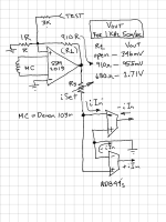
This brings up the subject of feedback. It seems that most moving coil head amplifiers don't employ feedback. I am not sure if Bonsai lists any with feedback on his website. This questions the sonic merit of devices like the SSM2017(19) that use feedback. To that end some. experiments were conducted to examine the merits of imposing what can concluded as positive voltage feedback to diminish the internal negative current feedback inherent in this device. The network below was applied to a balanced two stage current mode RIAA network comprised of 4 AD844's buffered with an NE5532. This feeding a Topping PA5 having balanced inputs. The input stage appears as the following:

Using a test record providing a 1KHz signal at 5cm/sec the output increased in amplitude from about 350mV to about 950mV using a 910 Ohm resistor (note the resistive division to the positive terminal with a minimalist 1 Ohm resistor to ground), this rose to about 1.7Volts using a 680 Ohm feedback resistor. Using a Denon producing about 0.3mV, the gain without a feedback resistor is about 1200, with a 910 Ohm feedback resistor the gain rises to 3200, and to 5700 for a 680 Ohm value.
The topology can be considered to combine negative feedback CFA operation with that of positive feedback VFA, whereupon negative feedback is higher speed and the positive feedback mechanism can alternatively be considered a low bandwidth signal source happening to connect from the output. Notwithstanding the adherence to the propriety of any conventions specific to CFA or VFA there seems a sonic correlation to optimal values of feedback as such relates to amplifying signals at the MC levels, feedback that is hence neither "zero" nor of a value normally provided by the SSM2017(9)'s.
An aspect of increasing gain is that the bandwidth reduces as a consequence, reducing to 30KHz with a 910 Ohm resistance and around 5KHz (as I recall) for the 680 Ohm feedback. This correlates inversely to increasing negative feedback reducing gain and causing frequency extension.
Suffice it to simply state for now that sonics appeared best with a value between 910 Ohm to around 1K Ohm in the totality of this implementation. At 910 the output of the SSM2019 was often close to the overloading limits in the presence of high amplitude high frequency signals yet never recognized of having any negative imposition on material listened too.
- Home
- Source & Line
- Analogue Source
- Fully balanced MC phono preamplifier thoughts