The Diode Inc. factory spice models are too optimistic for RB.I've been using models in Microcap 12 for the ZTX851/951.
For the ZTX851 RB should be 1.5 and for the ZTX951 RB should be 1.2.
This conforms with Horowitz&Hill and results in reliable figures.
Hans
Hi Hans
Don't be sorry for questions, I am very happy you looked at it and asked.
Even I'm building audio for long, it is in big campaigns with decates in between. I'm newby in many ways, including measuring.
I'll put together reply tonight when at my pc, probably with more questions than answers
Don't be sorry for questions, I am very happy you looked at it and asked.
Even I'm building audio for long, it is in big campaigns with decates in between. I'm newby in many ways, including measuring.
I'll put together reply tonight when at my pc, probably with more questions than answers

Yes that is true (I'm totally aware of that table in H&H}, but you also have an IE contribution too, so the effective noise resistance needs 25/IE added to Rbb' For a 5 ohm cartridge IE is around 3mA, so 25/3 = 8.3 ohms Lets add about 1.5 ohms for rbb' to get 9.8 ohms. The noise voltage contribution from that is around 400pV/rootHz. But there are two transistors electrically in parallel, so we divide by root 2 to get the noise contribution from the Duraglit arrangement to be 283pV/rootHz. The 5 ohm cartridge, as before, generates 288pV/rootHz - so the noise figure, agreeing with Lee's statement in the design notes, that the best NF is 3dB.The Diode Inc. factory spice models are too optimistic for RB.
For the ZTX851 RB should be 1.5 and for the ZTX951 RB should be 1.2.
This conforms with Horowitz&Hill and results in reliable figures.
Hans
The design current is cartridge resistance dependent. For 40 ohms is is about 0.3mA. By the above argument, the noise resistance is close to 83 ohms (let's therefore neglect rbb'!). The noise voltage is 1.2nV/rootHz. Divide by root 2 to get 830pV/rootHz. And the 40 ohm cartridge generates 814pV/rootHz. So again close to 3dB noise figure.
Craig
Last edited:
The only way to cheat the 25/IE is of course to parallel transistors. 4 in parallel in NPN and PNP reduces that noise source by a factor of 2. This was usually done in the days where the best show in town had fairly high rbb', dominating the 25/IE contribution. So many transistors were paralleled for that reason.
Craig
Craig
It isn't clear as to the extent one needs to be concerned with noise.
In the past, seemingly in the millennium of my own experience with moving coil phono stages, they have all been moderately to the more extremely noisy (I haven't found a step up transformer that I could live with for whatever reasons). IMO many of these phono stages, including those with paralleled FET and tube implementations, where found considerably better than those having little or no noise. Ultimately noise was always the subject of a tradeoff (like most everything else) for some perceived sonic virtue real or imagined, oftentimes easily to hear through. Background noise, as perhaps by a loved one as well, can be perhaps dangerously ignorable.
I am currently experimenting with the SSM2019, trying to push that to the limit. In keeping with the thread and the contributors to it, the phono stage has evolved in the balanced form:

Although not indicated in detail in the applications, the SSM2019 can be configured in a combined current/voltage feedback mode, with the MC connected to the gain terminals. This relies upon the floating coil nature of the cartridge ultimately operating at about -0.61 volts. It should be noted that the network shown was powered by +/- 8.5 Volt shunt regulators to limit fault currents. In the testing with voltage feedback gain setting to about 100x (180R/1R8) the actual voltage output was about 46mV for 1KHz at 5 cm/Sec using a Denon 103R. However the Denon indicates 0.25 mV, that for 46mV results in a gain of about 180. H'mm.
The advantage of this connection is that the gain can be reduced while maintaining the noise performance, as noise deteriorates when using an increased gain setting resistor between the gain setting terminals. In the case above, the resistance remains at 14 Ohms of the Denon 103R. The caveat relates to stability margins. With the cartridge connected the network was tested by injecting a square wave test signal being divided at the +ve terminal. In open loop form (without the 180 Ohm feedback resistance) the network is underdamped as expected. With the 180 Ohm resistor the network can be considered mostly critically damped. When reduce to 47 Ohm the network exhibits ringing of perhaps 5 cycles, meaning getting close to oscillations.
It should be noted that in the absence of voltage feedback the current feedback mechanism lowers the characteristic impedance at the gain setting nodes, more or less fixing what the network perceives as error currents. The application of voltage feedback raises the characteristic impedance of the gain setting nodes. Hence the network is a form of pseudo current/voltage feedback amplifier.
In the past, seemingly in the millennium of my own experience with moving coil phono stages, they have all been moderately to the more extremely noisy (I haven't found a step up transformer that I could live with for whatever reasons). IMO many of these phono stages, including those with paralleled FET and tube implementations, where found considerably better than those having little or no noise. Ultimately noise was always the subject of a tradeoff (like most everything else) for some perceived sonic virtue real or imagined, oftentimes easily to hear through. Background noise, as perhaps by a loved one as well, can be perhaps dangerously ignorable.
I am currently experimenting with the SSM2019, trying to push that to the limit. In keeping with the thread and the contributors to it, the phono stage has evolved in the balanced form:
Although not indicated in detail in the applications, the SSM2019 can be configured in a combined current/voltage feedback mode, with the MC connected to the gain terminals. This relies upon the floating coil nature of the cartridge ultimately operating at about -0.61 volts. It should be noted that the network shown was powered by +/- 8.5 Volt shunt regulators to limit fault currents. In the testing with voltage feedback gain setting to about 100x (180R/1R8) the actual voltage output was about 46mV for 1KHz at 5 cm/Sec using a Denon 103R. However the Denon indicates 0.25 mV, that for 46mV results in a gain of about 180. H'mm.
The advantage of this connection is that the gain can be reduced while maintaining the noise performance, as noise deteriorates when using an increased gain setting resistor between the gain setting terminals. In the case above, the resistance remains at 14 Ohms of the Denon 103R. The caveat relates to stability margins. With the cartridge connected the network was tested by injecting a square wave test signal being divided at the +ve terminal. In open loop form (without the 180 Ohm feedback resistance) the network is underdamped as expected. With the 180 Ohm resistor the network can be considered mostly critically damped. When reduce to 47 Ohm the network exhibits ringing of perhaps 5 cycles, meaning getting close to oscillations.
It should be noted that in the absence of voltage feedback the current feedback mechanism lowers the characteristic impedance at the gain setting nodes, more or less fixing what the network perceives as error currents. The application of voltage feedback raises the characteristic impedance of the gain setting nodes. Hence the network is a form of pseudo current/voltage feedback amplifier.
May I be so free to correct you slightly.Yes that is true (I'm totally aware of that table in H&H}, but you also have an IE contribution too, so the effective noise resistance needs 25/IE added to Rbb' For a 5 ohm cartridge IE is around 3mA, so 25/3 = 8.3 ohms Lets add about 1.5 ohms for rbb' to get 9.8 ohms. The noise voltage contribution from that is around 400pV/rootHz. But there are two transistors electrically in parallel, so we divide by root 2 to get the noise contribution from the Duraglit arrangement to be 283pV/rootHz. The 5 ohm cartridge, as before, generates 288pV/rootHz - so the noise figure, agreeing with Lee's statement in the design notes, that the best NF is 3dB.
The design current is cartridge resistance dependent. For 40 ohms is is about 0.3mA. By the above argument, the noise resistance is close to 83 ohms (let's therefore neglect rbb'!). The noise voltage is 1.2nV/rootHz. Divide by root 2 to get 830pV/rootHz. And the 40 ohm cartridge generates 814pV/rootHz. So again close to 3dB noise figure.
Craig
The total transistor input noise is caused by Rbb+1/2Gm and not Rbb+1/Gm
The value to add to Rbb is thus 1/2Gm or 25/(2*IE) which calculates into 25/6 for 3mA. resulting in 1.5+4.2 = 5.7R.
This 5.7R generates 308pV/rtHz
With two transistors in parallel this becomes 218pV/rtHz for the Duraglit alone.
the 5R alone generates 288pV/rtHz so in total this should result in 361pV/rtHz.
Hans
That is absolutely right. How did I miss including that factor of 2? Brain fog.
Craig
Craig
Well, in your picture the cart is no longer floating...Looking at the input network as outlined by STEP RESPONSE it isn't clear that this is the best approach to achieve a balanced output using a pair of AD844's. An alternative approach would configure the network as per below:
View attachment 1348175
The moving coil cartridge is a floating source. As far as the upper AD844 is concerned the voltage developed across the inputs is a function of the input current imposed on ~50 Ohm input impedance as specific to the +ve terminal of the AD844. This potential also appears across the lower AD844, however this generates equal opposing currents through the ~50 Ohm into the terminal connected to ground. It seems likely this parallel connection would generate considerably less noise (and you can always start stacking too...).
The upper 844 is working in 'current mode' and the lower in voltage mode.
Any possible advantage of balanced operation is lost.
Trying to wrap my head around the floating arrangement between the tz nodes.
It's a bit like a X connection à la Pass, but without a path to gnd to put things in a well defined state.
It's late, I'll have to ponder this tomorrow.
It seems likely that others can explain this better, but suffice it to suggest that a cartridge having a coil with two ends isolated from another reference point or node can have either end referenced to a third node in the absence of current flowing in or out of that reference node. Problems arise if multiple paths exist causing signal noise currents to be imposed along the length of one or more signal lines. The original diagram shows a single point ground node that is common to three other points, meaning that ground can be considered an innocuous reference point as mostly not carrying any current affecting balanced operation. To be clearer this ground node can also be moved as below:

"The upper 844 is working in 'current mode' and the lower in voltage mode." With the ground reference moved as shown, the lower can be observed working in current mode as well. In the lower AD844 the current is being sourced from the seeming opposing end of the coil. In this connection there are two 50 Ohm inverting terminal input impedances in parallel across the MC or 25 Ohms (this in comparison to 100 Ohms in series). It should be noted that the 2 x 10K Ohm resistors develop any imbalance currents that shift the input operating point.
"The upper 844 is working in 'current mode' and the lower in voltage mode." With the ground reference moved as shown, the lower can be observed working in current mode as well. In the lower AD844 the current is being sourced from the seeming opposing end of the coil. In this connection there are two 50 Ohm inverting terminal input impedances in parallel across the MC or 25 Ohms (this in comparison to 100 Ohms in series). It should be noted that the 2 x 10K Ohm resistors develop any imbalance currents that shift the input operating point.
Dear Hans;

See If above correction might lead to closer match. My conclusion is to continue measurements with real cart when ready as I cant measure real input V (just Rin from instrument is too high to get anything accurate from this RMS level).
PS, there is also strange hill at approx 23000 Hz that should not be there since I measure at 192/24, not 44/16. Another thing I could not figure is how to save RTA measurement in REW so I can later review settings, I only save pictures.
This picture could also give some clues on first question: this is guaranteed 1 V in , 1 V out closed loop soundcard, I,m sure I measured the preamp with exactly same RME and REW settings:

For sanity check, I saved some pictures of preamop Voltage measurements without signal. (be aware these I was making with 100 kHz bandwidth, my mistake)
This was SSM2017 in normal voltage mode:

No preamp, soundcard closed loop :

From preamp that has no power (batteries disconnected):

From powered working preamp, inputs opened:

Powered preamp, inputs plugged in RME outputs, but no signal generated:

Calculated noise about 200nV, measured about 100nV in LF, in HF climbing as discussed above.
Does this make any more sense to you now? If yes please share to my eager ears 🙂
I think that I left 2 x 8k2 resistors attached from Rg to ground, like I did in previous run of tests but I don't know now, as I'm away I cant check physical device. If you replace 2x 4k87 with 2 x 47k, this should be correct:A Cart, operating in current mode, is represented by Rg=33R giving a gain of 10K/33R = 303 or 49,6dB.
Signal on Cart is from a 1Volt@1Khz source, fed through two 47K resistors on Rg, causing 0.35mV on Rg.
With the calculated gain of 303 this should result in106mV, which corresponds nicely to within 0.77dB with the -20.26dBFS as shown in the image .
But the spectral 1Khz line in your Image is at -11.19dBV, or at 276mV, which is 2.8 times or 9.07dB higher as the -20.26dB, but nevertheless the -11.19dB was used to calculate the S/N.
There must be something I'm missing here in the calculation
See If above correction might lead to closer match. My conclusion is to continue measurements with real cart when ready as I cant measure real input V (just Rin from instrument is too high to get anything accurate from this RMS level).
This is real mystery to me, it is not related to preamp measured here, but to my measurement system. It is like this with everything I measure, se below picture of RME in closed loop. Is it my PC or its USB, or something I made wrong in settings? Only thing that is constant in all my playing is PC and REW on it. I get similar but less exaggerated climb in noise also with USB microphone (w/o RME) , hitherto for that I accused environment noise...The other thing I don't understand is the shape of the noise spectrum in the image which increases by almost 30dB from 20Hz to 20Khz, while the SSM2017's spectrum as shown in the attachment goes down with increasing frequency ?
PS, there is also strange hill at approx 23000 Hz that should not be there since I measure at 192/24, not 44/16. Another thing I could not figure is how to save RTA measurement in REW so I can later review settings, I only save pictures.
This picture could also give some clues on first question: this is guaranteed 1 V in , 1 V out closed loop soundcard, I,m sure I measured the preamp with exactly same RME and REW settings:
I am aware, at the same time I can 100% confirm that connection was as in picture above + 2x 9V batteries.This can be confirmed by a quick check.
The SSM2017 produces ca. 1.5nV/rtHz at a gain of 303.
For a BW from 20Hz to 20Kz this results in sqrt(20Khz)*1.5nV/rtHz = 212nV.
For a cart producing 0.35mV, S/N now becomes 20*log(0.35mV/212nV) = 64.4dB without Riaa and without A-weighting.
With Riaa this becomes ca. 70.4dB and with added A-weighting ca. 74.4dBA.
For sanity check, I saved some pictures of preamop Voltage measurements without signal. (be aware these I was making with 100 kHz bandwidth, my mistake)
This was SSM2017 in normal voltage mode:
No preamp, soundcard closed loop :
From preamp that has no power (batteries disconnected):
From powered working preamp, inputs opened:
Powered preamp, inputs plugged in RME outputs, but no signal generated:
Calculated noise about 200nV, measured about 100nV in LF, in HF climbing as discussed above.
Does this make any more sense to you now? If yes please share to my eager ears 🙂
@Drbulj,
First the spectra that are shown.
I think I can see why your noise is increasing with frequency.
It’s because what is dispayed are parts of an octave, 1/48 to be precise, and not fixed frequency bins as the usual way to display.
As an example, an octave at 50 Hz goes to 100Hz and at 5Khz to 10Khz.
Suppose you have 1nV/rtHz, then from 50Hz to 100Hz you have sqrt(50)*1nV = 7.1nV but from 5Khz to 10Khz you will see 71nV or 20dB more noise.
So, when working with octaves or parts of octaves, the noise spectrum will go up with 10dB/decade.
Switch it off and you will see the flat spectrum that is more meaningful.
Hans
Most of that went right over my head...english is not my native language.It seems likely that others can explain this better, but suffice it to suggest that a cartridge having a coil with two ends isolated from another reference point or node can have either end referenced to a third node in the absence of current flowing in or out of that reference node. Problems arise if multiple paths exist causing signal noise currents to be imposed along the length of one or more signal lines. The original diagram shows a single point ground node that is common to three other points, meaning that ground can be considered an innocuous reference point as mostly not carrying any current affecting balanced operation. To be clearer this ground node can also be moved as below:
View attachment 1348302
"The upper 844 is working in 'current mode' and the lower in voltage mode." With the ground reference moved as shown, the lower can be observed working in current mode as well. In the lower AD844 the current is being sourced from the seeming opposing end of the coil. In this connection there are two 50 Ohm inverting terminal input impedances in parallel across the MC or 25 Ohms (this in comparison to 100 Ohms in series). It should be noted that the 2 x 10K Ohm resistors develop any imbalance currents that shift the input operating point.
That drawing helped though 🙂 now I see what you meant, clever way of reducing perceived input Z.
It seems likely that others can explain this better, but suffice it to suggest that a cartridge having a coil with two ends isolated from another reference point or node can have either end referenced to a third node in the absence of current flowing in or out of that reference node. Problems arise if multiple paths exist causing signal noise currents to be imposed along the length of one or more signal lines. The original diagram shows a single point ground node that is common to three other points, meaning that ground can be considered an innocuous reference point as mostly not carrying any current affecting balanced operation. To be clearer this ground node can also be moved as below:
View attachment 1348302
"The upper 844 is working in 'current mode' and the lower in voltage mode." With the ground reference moved as shown, the lower can be observed working in current mode as well. In the lower AD844 the current is being sourced from the seeming opposing end of the coil. In this connection there are two 50 Ohm inverting terminal input impedances in parallel across the MC or 25 Ohms (this in comparison to 100 Ohms in series). It should be noted that the 2 x 10K Ohm resistors develop any imbalance currents that shift the input operating point.
in a simulation the A weighted noise has been reduced just as expected from 4usec to 2usec RTI, so S/N for a 0.3mV 5R cart has been bettered from 37dBA to 43dBA, an improvement but still way below the minimal required 60dBA to stay below the LP's surface noise.
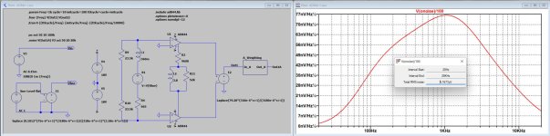
So to use this circuit, one may need a MM Cart with at least 20dB more output, so let's give it a try.
But In this configuration a MM Cart will have a problem with the Rin = 50R termination, because this Rin will cause a new time constant at Tc = Lcart/(Rcart+Rin), which will interact the 75usec time constant.
For a 4mV AT150 MM as an example with Lc=360mH, Rc= 665R and Rin=50R this would cause a pole at 1/(Tc*2Pi)=316Hz, so better to use the 100R input resistance giving a pole at a slightly higher 338Hz.
Now we have to shift this 470usec pole to 75usec for which we need to completely change the compensation network at the 844's T connection.
Having given the complete circuit a gain of 40dB, the measured noise is now 5.17uV RTI, see attachment.
The S/N for this combination is now 20*log(4mV/5.17uV) = 57.8.
So even for an MM this topology with the AD844 is hardly the proper solution.
Hans
Attachments
Why are you applying a mic calibration file?This is real mystery to me, it is not related to preamp measured here, but to my measurement system.
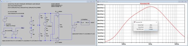
I finally tried with a resistor in series with the Cart to cause a Tc of 75usec by Lc/(Rc+Rin) = 75usec instead of the previous 470usec.
For that I had to insert a additional 4.135K resistor to the existing Rc=665R and Rin=50R.
I also used the topology with both + inputs connected to the crossed - inputs to get Rin=50R which improves on noise.
The connection between both T outputs is now just a resistor to set the gain and the Carts coil with the added 4.135K resistor takes now care of the 75usec pole.
Noise RTI is now 3.23uV, so S/N becomes now 20*log(4mV/3.23uV) = 61.8dBA.
It's not the sky, but this is finally an acceptable figure.
So here is the end of my attempts to get a working solution with this configuration.
Hans
Attachments
- Home
- Source & Line
- Analogue Source
- Fully balanced MC phono preamplifier thoughts