For a headamp being used in front of a Riaa MM amp, gain has to be settable somewhere between 20dB and 40dB max.
So a headamp in that case surely needs a gain setting provision depending on the MC Cart’s resistance.
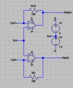
With the topology in the attachment, gain can be set with R14 / R5 for a transimpedance topology.
The two (discrete) amp’s should of course be low noise types, again depending on the Cart used.
Hans
So a headamp in that case surely needs a gain setting provision depending on the MC Cart’s resistance.
With the topology in the attachment, gain can be set with R14 / R5 for a transimpedance topology.
The two (discrete) amp’s should of course be low noise types, again depending on the Cart used.
Hans
Attachments
Distortion is always of critical concern Hans. Non-correlated random noise not so much if "acceptably" low. Many head-amps don't use feedback. In the case of the SSM2019 imposing internal negative feedback the amount of positive feedback applied can still result in a condition with net overall negative feedback, hence potentially less odd distortion than a no feedback alternative. No idea what the net odd distortion products are in this, or in the subsequent RIAA stage, rather both networks were adjusted by ear, being not necessarily to minimize distortion in the tradeoff with other artifacts.@Hierfi
Drawback from using this positive feedback is that odd distortion products are rapidly rising depending on the amount of feedback.
No idea how much this is for the SSM1019 in your specific situation.
Hans
Amplification in the pre-RIAA creates a condition whereupon distortions roll off at almost at 6dB/octave above the first 50 Hz RIAA pole. In the case of an amplifier with a symmetric non-linear transfer function a non-linearly variant fundamental that is normally hidden within a steady state sinusoidal test signal is higher than normal after being subjected subsequently to an RIAA, being suspected of creating overly dynamic or alternatively compressive sonic characteristic dependant upon its phase in relation to the undistorted linearly variant fundamental, being either rising additive or falling subtractive. I suspect this manifests as an overly aggressive character or alternatively a compressive character in the higher dynamic passages.
"For a headamp being used in front of a Riaa MM amp, gain has to be settable somewhere between 20dB and 40dB max.
This can be a cost saving measure, seemingly could be better done with independent amplification optimized for MM and MC cartridges feeding a common RIAA stage optimized to operate in its best operating window. The basic concept is below. Using an inverting terminal input to the RIAA allows for a wide range of current gain adjustment to the RIAA.

Creating an operating window was found particularly important in the network using a quad of AD844's performing an open loop balanced RIAA function, Particular care is required to limit the extent the signal operates over the non-linear transfer function of the input devices of the AD844's, for reasons of minimizing the magnitude of odd distortions created. With or without feedback the non-linearity that is manifest conforms to the principle that in any reduction of differential signals over a fixed non-linear transfer functions the signal operates over an effectively straighter portion of that transfer function, hence reducing distortion. However by reducing input signal swings, other artifacts can become more dominant in the network, also being increasingly sensitive to external influences that can corrupt performance. In other words, there is a tradeoff to the point odd distortions can be acceptably low comparatively, though not necessarily non-existent.
Below is more complete diagram of the MC phono preamplifier showing some more measurements for 1KHz 5cm/sec. In this the input stage of the RIAA is shown operating with input currents at around 160uA, feeding of frequency limited current into the subsequent stage. This current is significantly higher than currents fed from a MC cartridge, currents resulting in the poor noise performance that you determined Hans. I suspect noise performance would be somewhat beyond the minimum 60dBA in this network. Certainly lifting the stylus from the mostly "supposed" silent grooves results in subjectively near zero noise. It should be noted that the RIAA network was "loosely" adjusted.


Wow, that’s a complex but interesting circuit.
It doesn’t follow in any way the usual road, just read that as a compliment.
Hans
It doesn’t follow in any way the usual road, just read that as a compliment.
Hans
Last edited:
The network of post #282 was simplified to eliminate a pair of AD844's by splitting the 6K Ohm current gain set resistor with two 3K Ohm values and adding an approx. 47 nF capacitor at the juncture to ground. The output of the SSM2019 and the inverting input of the AD844 both form AC grounds for the 75uSec time constant, whereupon the parallel combination of R1/R2 in combination with C1 thereupon creates the RC time-constant at the juncture, being proportionately sensed of a filtered response as current through R2 feeding the inverting input. The 910 Ohm was actually reduced to 820 Ohms below, increasing the output of the SSM2019 to about 1.1V RMS for 1 KHz 5 cm/Sec or about 1.5dB for sonic reasons.

Last edited:
I’m still puzzled by one thing, that’s the use of an additional NE5532 as a buffer.
Why not use the AD844’s internal buffer that is connected anyhow to the 50/500 network.
Hans
Why not use the AD844’s internal buffer that is connected anyhow to the 50/500 network.
Hans
Many have used this output, though I wouldn't recommend it. Keep in mind that the internal buffer has no overall feedback in this network, hence there is no mechanism to correct crossover distortions resultant from the limited quiescent bias currents that can also be called upon to drive capacitive cabling. Of note too is that the middle of the diamond is dynamically driven (not a constant current source), being also mirrored from the inverting input current as is the Tz node. This is done to support the 2000V/uSec slew rate. Under normal feedback conditions the inverting terminal dynamic currents become drastically reduced as difference currents reduce to the current needed to drive the 2-3 Meg Ohm 5 pF Tz node impedance, as ultimately driving the output buffer. This Tz node impedance is replaced herein by far lower resistances and/or much higher capacitances imposed by the RIAA, with the full magnitude of those currents being also continuously reflected into the middle of the diamond buffer as well. It isn't clear as to the degree the output follows the Tz node under such conditions, being traditionally constant current sources in many implementations containing such buffers.
At one time I tried using the output buffer of the AD844 on its own, feeding signal directly into the Tz node, grounding the +ve input terminal and leaving the -ve input open circuit as below.

Leaving the inverting terminal disconnected neutralizes current variance in the mirrors, becoming instead constant current sources feeding the Tz node and creating constant current sources in the mid points of the diamond buffer as well. However, it was found that if the network includes capacitance from the Tz node directly to ground (this in absence of minimum value of R1), this resulted in high frequency instabilities. Given the absence of overall feedback this suggests the instability is related to mechanisms within the output buffer itself. Ultimately a minimum resistance of around 50 Ohms is required in series with the Tz node if significant capacitance exists to ground. This is independent if the output buffer is an open circuit and unused. Such marginal instabilities often leads to distortions or a lack of resolution and/or focus, sonics that this buffer is at least suspect of having.
In lieu of using the output buffer in the AD844 the NE5532 was tested as a substitute along with a number of alternative duals. Devices tested, amongst others, included an LT1364 and an LM6172 (both VFA's with CFA performance), an LT1469 (having an inverted NPN/PNP topology similar in form to the AD797 (though with higher noise), and an LM4562. The LT1469 was marginally unstable (showing oscillations in the output), as likely the result of poor power supply decoupling on my part. Nevertheless, the requirement of power supply decoupling is in my view concerning in that elements to support stability must be active to do so, being then dependant upon the nature and quality of capacitive components involved in what can be a convoluted loop back to ground. The sonic implications are not clear and hence oftentimes avoided of using such devices. This is not to suggest that alternative measures couldn't be taken to adequately control stability by other means.
The LT1364 appears the best choice overall. Sonics are good, perhaps because of the wide-band speed and fast slew rate, with internal RC compensation from its output back to an internal Tz node, the reason likely making it a good choice for cable drive, as being recommended for this. I look for low impedance output drive as a means of driving cables of variant dielectric materials. The principle being that a zero output impedance replaces electrons lost in dielectric materials or alternatively takes in electrons re-entrant from those materials without changing the voltage signals feeding subsequent networks. In the case of the LT1364 the Ro extends to over 30 KHz at around 0.02 Ohms (as a guess from the data sheet) if the device is connected in unity gain. Unfortunately it isn't as cheap as I would like...
At one time I tried using the output buffer of the AD844 on its own, feeding signal directly into the Tz node, grounding the +ve input terminal and leaving the -ve input open circuit as below.
Leaving the inverting terminal disconnected neutralizes current variance in the mirrors, becoming instead constant current sources feeding the Tz node and creating constant current sources in the mid points of the diamond buffer as well. However, it was found that if the network includes capacitance from the Tz node directly to ground (this in absence of minimum value of R1), this resulted in high frequency instabilities. Given the absence of overall feedback this suggests the instability is related to mechanisms within the output buffer itself. Ultimately a minimum resistance of around 50 Ohms is required in series with the Tz node if significant capacitance exists to ground. This is independent if the output buffer is an open circuit and unused. Such marginal instabilities often leads to distortions or a lack of resolution and/or focus, sonics that this buffer is at least suspect of having.
In lieu of using the output buffer in the AD844 the NE5532 was tested as a substitute along with a number of alternative duals. Devices tested, amongst others, included an LT1364 and an LM6172 (both VFA's with CFA performance), an LT1469 (having an inverted NPN/PNP topology similar in form to the AD797 (though with higher noise), and an LM4562. The LT1469 was marginally unstable (showing oscillations in the output), as likely the result of poor power supply decoupling on my part. Nevertheless, the requirement of power supply decoupling is in my view concerning in that elements to support stability must be active to do so, being then dependant upon the nature and quality of capacitive components involved in what can be a convoluted loop back to ground. The sonic implications are not clear and hence oftentimes avoided of using such devices. This is not to suggest that alternative measures couldn't be taken to adequately control stability by other means.
The LT1364 appears the best choice overall. Sonics are good, perhaps because of the wide-band speed and fast slew rate, with internal RC compensation from its output back to an internal Tz node, the reason likely making it a good choice for cable drive, as being recommended for this. I look for low impedance output drive as a means of driving cables of variant dielectric materials. The principle being that a zero output impedance replaces electrons lost in dielectric materials or alternatively takes in electrons re-entrant from those materials without changing the voltage signals feeding subsequent networks. In the case of the LT1364 the Ro extends to over 30 KHz at around 0.02 Ohms (as a guess from the data sheet) if the device is connected in unity gain. Unfortunately it isn't as cheap as I would like...
Last edited:
Thx, interesting to read this all.
Since most interlinks have approx a ca. 100R caracteristic impedance, it is good practice to put the same 100R in series with the cable or with differential outputs two 50R resisistors to suppress cable reflections happening at much higher frequencies.
Those reflections happen because the receiving side with a much higher impedance acts as an open end.
Have you ever tried tried this instead of aiming for the lowest possible output impedance ?
In theory with zero ohm at one end and an open termination at the other side, reflections once started will go on and on and may well pollute the audio signal.
Hans
Getting back to this for a moment, I was employed in the Electronics Shop in Engineering for decades, serving not only all manner of research at Western as a whole, but industrial research outside as well, whereupon many things are radically unusual.Wow, that’s a complex but interesting circuit.
It doesn’t follow in any way the usual road.
A case in point was creating an electro-mechanical device to auto-ejaculate primates to collect semen... this for whatever reason. What I can't figure out... something that I can't figure out to this day... and I am sure there are good reasons for this not clearly explained... why the research assistants refused to work with their hands...
🤣What I can't figure out... something that I can't figure out to this day... and I am sure there are good reasons for this not clearly explained... why the research assistants refused to work with their hands...

Science is demanding 🤣😆Getting back to this for a moment, I was employed in the Electronics Shop in Engineering for decades, serving not only all manner of research at Western as a whole, but industrial research outside as well, whereupon many things are radically unusual.
A case in point was creating an electro-mechanical device to auto-ejaculate primates to collect semen... this for whatever reason. What I can't figure out... something that I can't figure out to this day... and I am sure there are good reasons for this not clearly explained... why the research assistants refused to work with their hands...
Brilliant case!
I was just curious to see what different well respected preamp manufacturers implemented for their output impedances.Since most interlinks have approx a ca. 100R caracteristic impedance, it is good practice to put the same 100R in series with the cable or with differential outputs two 50R resisistors to suppress cable reflections happening at much higher frequencies.
On average I got a figure of 75R over ten amps that I looked at.
Hans
... seems the veracity of my confusion might have come into some question Hans...
To the above you could add the output impedance of a Tenor Audio phono stage that Jim Fairhead manufactures. He is a truly nice guy and invited me and a friend to hear his audio gear in his sizeable three car garage, The system sounded great though the acoustics was somewhat marred, being flanked by a Porsche sports car on one side and a Ferrari on the other. Yet the retail of his audio gear was greater than the sum of the two. After a while it seems I might have taken on the appearance of someone more visibly inferior... oftentimes finding myself glancing down at my tattered goodwill shoes.
Anyway... enough of this self pity... his separate phono stage is listed below.
http://tenoraudio.com/high-end-audio/phono-1-ultimate-reference/specifications.html
The phono stage retails at $94,500 (I suppose not wanting to break the $100K barrier) Oddly it shows 10 Ohms SE and 100 Ohms balanced. His preamp doesn't show the output impedance retailing at $194,500 ($200K barrier?) or $289,000 in total for a preamp to play records.
http://tenoraudio.com/high-end-audio/line-1power-1-ultimate/specifications.html
Last edited:
Hierfi,
All those extreme prices are utterly nonsense.
But one may assume that the builder tried to get the best sound out of his gear and one of those parameters is the output impedance driving an interlink, so it can serve as a way to bring you to new ideas.
There lies the beauty of DIY.
One can simply do some trial and error to find an optimum.
That’s why I asked you in a previous poster whether you ever tried a higher output impedance.
The only person in the whole world who has to judge whether this improves the sound perception in your situation are you.
When zero ohm sounds better, voila.
Hans
Hans,
Keep in mind there are often hidden costs that can dramatically increase the consumer pricing... like Ferrari roadside repair...
But getting to your earlier post, 50 Ohm RG59 cable was prolifically used in Electrical Engineering (and seems still is). This normally consists of 50 Ohm cable terminated in 50 Ohm BNC connectors, being both sourced and terminated with 50 Ohm resistors. We actually had a time domain reflectometer to observe reflections, but I never used it for audio.
Low impedance termination to ground is rarely done in audio, perhaps because heavy loading can cause significant increases in distortion. Nevertheless I did try balanced terminated R/L pairs of BNC's for audio. This was years ago, and mostly because the cables also had teflon dielectric. Prior to this, cabling often consisted of twisted pairs of magnet wire, or copper inside of teflon extruded tubing with RCA connections. Both types of these cables are still in use. Respecting the RG59 cabling it didn't improve the sonics over either of these others, so this was abandoned.
I believe there is a strong influence related to dielectric materials, that driving out the influence of dielectric materials is helped by lowering the output impedance, consequently I added about 1 or 2 Ohms in series with most output amplifiers. Of note is that lowering the output resistance can cause peaking or destabilize of the output amplifier so this was tested. Coincidentally the LT1469 tested earlier was actually unstable because of the capacitive cable loading, becoming stable with 43 Ohms in series.
I have been experimenting with increased resistance in the output since you mentioned this in your post #228 Hans, having added 43 Ohms per side (the closest on hand). What was interesting was that adding resistance of this magnitude was not negative in the balanced mode, rather improved clarity and focus. This was unexpected, as SE was better with lower resistance. As a result I have left these resistors in and have been wondering why this might be the case.
Tenor is a company considered extremely focused on sonics (and aesthetics) and seems making decisions dominantly on that, although they have extensive measurement equipment. This is to say they could have just as easily used 50 Ohms instead of 10. The question becomes why SE at 10 Ohms and balanced at 100 Ohms? Nearly everyone else uses a 1:2 ratio except Dan Dagostino and Boulder (in your listing). At 2 Ohms it hardly matters and at 100 Ohms this questions if Boulder knows or cares. Perhaps (just like a vast number or others), they do so solely for stability reasons and to provide a means to current limit the output for muting purposes, shorting the output to ground.
For me the question is why does a higher resistance like 43 Ohms seem to work fine in balanced? Although it might be the result of reflections, it seems more likely caused by an increase in the stability margins of the output amplifier coupled with a reduction in dielectric influences. Having a symmetrical cross-section of cabling being fed by differentials creates a constant net zero field to the surrounding shield ground, perhaps reducing the capacitive attraction of electrons toward what could be a large shield, perhaps with dielectric effects further cancelled by the differential receiver? Pure speculation on my part Hans. Don't know for sure, though I am leaving the resistors in.
Hi,
Small comment from my side, putting resistors in series of balanced output is also practice on many pro gear too, expected to drive long cables = high capacitance. Out of my head; my demon pro surround preamp has 200 ohms on each leg.
Small comment from my side, putting resistors in series of balanced output is also practice on many pro gear too, expected to drive long cables = high capacitance. Out of my head; my demon pro surround preamp has 200 ohms on each leg.
I think the prices include the advertising cost which if you don't do, you will be left behind, even if your product sounds great...Hierfi,
All those extreme prices are utterly nonsense.
Krell experimented with transimpedance main amps, transferring just current from the preamp through the interlink ending in a zero ohm virtual input.Low impedance termination to ground is rarely done in audio, perhaps because heavy loading can cause significant increases in distortion.
Although a promising apoach, it deviated too much from the standards in the industry and was abandoned as far as I know.
Now with MC Carts you see transimpedance coming back in several phono preamps.
When trying to use coax with voltage amps, using the right termination, you will have all HF reflections well under control, however in the LF Audio range, coax cables are not sounding very well.
You want the best possible sound in the audio range, where every cable and cable length has it’s own signature
There are several things coming together that may even be conflicting.
1) to get the flattest possible frequency transfer, your preamp should have near zero output impedance
2) but to keep your preamp stable because of the Interlinks capacity, you may have to insert a serial resistance
3) that’s why a low capacity Interlink seems to be beneficial, but for whatever reason, you may prefer the sound of a cable with a higher capacity
3) to absorb reflections, you either keep your interlinks short which is not always possible or use a serial resistance.
So in the end, depending on the personal situation, if wanting to find the optimum, it’s a process that takes time.
Change one element, preamp, cable, main amp or whatever and you may have to start all over from scratch.
It’s very interesting that you found different resistances for SE and for Balanced.
Some people even prefer SE in all situations, although several preamps in my list do not even have SE outputs.
It is a very controversial topic on this forum but different interlinks can make large differences in sound perception, so when you didn’t use one and the same cable for comparing SE to Bal, in case of SE with a SE to Bal adapter on one end and a Bal to SE adapter at the other end, the outcome of your test may be influenced by cable differences.
And keep in mind that not every difference in sound can be technically explained.
When that would be possible, all amps in the world would produce the same sound.
Hans
Sorry, Denon, not demon 🙂Out of my head; my demon pro surround preamp has 200 ohms on each leg.
- Home
- Source & Line
- Analogue Source
- Fully balanced MC phono preamplifier thoughts