"Electronics and instrumentation have changed considerably since 1967 but the concepts of grounding and shielding have remained constant." This is contained in the third edition (1986(?)or about 40 years ago now) of "Grounding and Shielding Techniques in Instrumentation" by Ralph Morrisson. The concepts disclosed in this book were difficult to understand back then, perhaps even more difficult to many now. This appears the case for many diyer's that rely on simulators as the test mechanism to create pc boards, having little or no access to measurement instruments to verify results in the real world.These discussions will go on forever because we have no real working definitions of "balanced" and "ground". Both terms really need to be shot in the external hearing undiffusor and replaced with a better model.
All good fortune,
Chris
The difficulty in using simulators, particularly for SE networks, is that ground lines appear as single nodes and don't indicate the impact of ground loop currents. Back in the days of "RCA's" and SE networks there existed a need to mitigate the effects of ground currents using star grounding and series ground sequencing, otherwise all sorts of difficulties arose, including oscillations.
In reality ground is not a single node. Balancing can increase the probability of a more successful outcome if one lacks the background to implement an SE network that handles grounds and power supplies with competence, perhaps reinforced by measurements. It helps to keep in mind that in the debate of "balanced" vs "SE" it can be asserted that balanced is better than SE. This is born out by depictions by ASR on most devices they test. Yet balanced is not better to SE when looking at the results when looking at differing devices. Many SE devices can be dramatically superior to balanced devices by different manufacturers. In both cases you need to know what you are doing to achieve the technical results like those devices created by companies such as Topping and SMSL.
@Bonsai, sorry if I'm bothering you with my new obsession. I feel like infant just talking about one subject
Still on cart loading with trans impedance head.... Read many papers in meantime, but also many reviews where almost all recommend very low output (meaning low R source too) carts for current mode amp.
Same as on audio Xpress article from your site about X Altra.
This is from first page
The MC preamplifier stage is best suited to
cartridges with output currents in excess of 12μA (no reference on which frequency, I guess RMS then)
On 5th page there is table with carts; your DL-103 mentioned as Rsource 30 ohm (as you earlier said to measure, spec is 40 ohm but for Z, depending on F all ok and within tolerances). Also 0.39 mV output at 1kHz (spec from Stereophile review is 0.25 mV)
Then it says 11.7 microA capable @1kHz: By ohm law that would be 33.4 Ohm to produce.... In general specs Denon did not recommenced load value for it, at least I did not see. But 33 ohm is at very low end of usual MC loads.
If I put published specs and say usual 100Ohm load, Denon is outputting only 2.5 microA
Now, according to same article and specs (that are more favorable than Denons specs that are avaliable) it is still marginally below recommended current capability, even with numbers stretched quite far from specs......?
My chart , according to spec and Benz recommendation (0.34 mV out @1kHz and 3.45 cm/s , recommended min load of 500 ohm, current is 0.85 micro A. Of course at given spec and recommended load... That would be completely out of recommendation (as would Dl-103 according published data) for any trans impedance amp from reviews I read. And naturally there are many carts similar to that.
Again excuses for drilling into one subject, what is your opinion; did all reviewers including Andrew C. Russell just by default recommend low Rsource carts to be transimpedanced, and that doesn't make any sense in real world of physics, or there is merit in their words?
Dear Hierfi,In reality ground is not a single node. Balancing can increase the probability of a more successful outcome if one lacks the background to implement an SE
This is a device that I'm working on while enjoining discussions here, It is made in early 2000's and audio signal of most of movies you watch and listen that are made in 2000's went through this (or just few similar) board for monitoring purposes, as mentioned somewhere before , these signals were never released to public in analog form. . The complete device costed new about 78000 US$, this is just monitor out and analog in board with DSP . Go and figure grounding scheme here. Only thing that is for sure, all analog signals on this are fully differential, not just balanced. Pls wait another 25 years for Topping and SMLS to get to this, even I think that they make very good products also today, but for very simple use. Politely I think we should end soon 🙂
Hi, the reason low Rsource carts make better ones for current injection MC preamps is simply that in general they produce higher output currents when used like this so you need less upfront gain, and ultimately this helps with lower noise. On A DL103 the output is 390uV and the published generator resistance 40 ohms, so this is about 10 uA. To calculate the output current, divide the specified output voltage by the specified coil resistance. So if your cart is 200uV and the coil resistance is say 10 ohms, the output current into a short (virtual earth) will be 20 uA. Note that in my table, I included my amplifier input resistance in the calculation so the output currents are a bit lower than you get from just the cart voltage divided by the cart resistance. If you use an opamp in MC current injection mode, the input resistance will be very close to 0 Ohms. In the X-Altra it’s about 3.5 Ohms. Note carefully, this is not acting as a voltage divider, but simply an additional resistance in series with the generator resistance.
I recommended carts with =>12 uA because that was the lower limit based on the DL103. Many MC carts are 5 to 10 ohm coil resistance and 200-500 uV output, so the output currents are high.
I recommended carts with =>12 uA because that was the lower limit based on the DL103. Many MC carts are 5 to 10 ohm coil resistance and 200-500 uV output, so the output currents are high.

Hi Bonsai, you got me just before bead, thanks, my understanding is getting to conclusion because of what you wrote:
Plus I'm getting the picture of diesel (LP-stylus) being not exactly so strictly connected to generator (coil - magnet). It starts to make sense.
Next I will be bothering the rest of the world including you and Hans as best victims 🙂 about making preamp to suit most MC's ( except hi out ones like Sumiko blue point, second one I have, that basically behaves as MM) . Could be interesting that preamp can vary input resistance, like from 2 to 50ish ohm (at expense of noise, which we all I think concluded is not relevant as long as it is under inherent LP stylus noise level....
Sorry for this, I think it is in best intention, if I'm confused , you can imagine how much average music loving audiophile is confused . Good for everyone to get better view and better preamp.
I go to sleep, thanks and good night!
ClearHi, the reason low Rsource carts make better ones for current injection MC preamps is simply that in general they produce higher output currents when used like this so you need less upfront gain, and ultimately this helps with lower noise
ClearOn A DL103 the output is 390uV and the published generator resistance 40 ohms, so this is about 10 uA. To calculate the output current, divide the specified output voltage by the specified coil resistance. So if your cart is 200uV and the coil resistance is say 10 ohms, the output current into a short (virtual earth) will be 20 uA
ClearNote that in my table, I included my amplifier input resistance in the calculation so the output currents are a bit lower than you get from just the cart voltage divided by the cart resistance.
Don't agree 🙂 . I'm mechanical engineer and economist by vocation , there is no very close in my world. If the figure is very small (or very large) one just moves comma sign to make them nice to view. At end it is all relative also in our case; If V is very small and I is very small, when you divide them it is again real number for R 🙂If you use an opamp in MC current injection mode, the input resistance will be very close to 0 Ohms
ClearIn the X-Altra it’s about 3.5 Ohms. Note carefully, this is not acting as a voltage divider, but simply an additional resistance in series with the generator resistance.
Plus I'm getting the picture of diesel (LP-stylus) being not exactly so strictly connected to generator (coil - magnet). It starts to make sense.
Next I will be bothering the rest of the world including you and Hans as best victims 🙂 about making preamp to suit most MC's ( except hi out ones like Sumiko blue point, second one I have, that basically behaves as MM) . Could be interesting that preamp can vary input resistance, like from 2 to 50ish ohm (at expense of noise, which we all I think concluded is not relevant as long as it is under inherent LP stylus noise level....
Sorry for this, I think it is in best intention, if I'm confused , you can imagine how much average music loving audiophile is confused . Good for everyone to get better view and better preamp.
I go to sleep, thanks and good night!
Hi,
.... except HiOut-MCs...... this is not necessarily so. INAs like the SSM, or TIs INA103/163, THATs 15xx that are all specced very similar (~1nV/vHz) typically show best noise behaviour at a optimal generator impedance around 200R.
Again, a fully differntial signal path inside of a device isn't superior in general, especially not when the designer did the grounding layout right.
Examples of such very flexible phono stages -in gain and load impedance- You can find everywhere here at diyaudio. On my website I discuss a number of proven good ones also.
jauu
Calvin
Hi,
The story is becoming much more transparent, at least for my calcified brain, for many others it was clear from the beginning 🙂
I think next step is ready; to design something that would nicely fit variety of true MC cartridges and be as robust as possible on external influences.
Now I'm convinced that excellent shortcut option is to call Bonsai and order X-Altra, done!
Alternative (please take this with humor) is to sell your car and by Ron Sutherland's Phono Loco, then sell the house to buy equivalently nice TT and chart and done too! There is some romantic beauty in listening such system nearby river, under the bridge 😎, save 5 euro for sunglasses.
But back to diy route; I would lie down few presumptions ; please challenge if you disagree:
1. It is not worth building universal MM/MC amp. Given the issue of changing carts (how many do that? as minimum one needs arm with detachable head shell) and relative ease of making phono preamp, the one that uses different carts should make dedicated preamps for them. Besides like this we can make only 2 stages, not MC head(or trafo) -MM preamp-Riaa-output amp
2. General layout as my handwritten sketch in post #65 is ok?
3. Passive RIAA? Or might be HF cut passive and LF boost in 2nd stage feedback?
4. For first stage I have tendency to use as high gain as possible, 2 times 60db (or 1000V/V) I achieved with 2x SSM2017 , giving differential output of x 2000v/v without any overload problems. At 0,34 mV (1khz) input, at 20kHz it is + 20db (3.4mV) x 1000 = 3.4 V. Nothing that amp with +-18 V PS should worry about. Overload margin is small but that is only at highest frequencies which are never recorded at 0db (otherwise our ears and tweeters would explode before clipping). But 3V battery supplies will not work for this.
Now back to my usual subject, praising Hans and Bonsai to havens! I have to stop that as its becoming embarrassing!
This time for MC Head Amp Circuit Compendium, yet another in a row of fantastic papers.
Here the circuit called after JJ Thompson drew my attention (how appropriate, guy discovered electron):
2 possible downsides:
How does it look to you?
The story is becoming much more transparent, at least for my calcified brain, for many others it was clear from the beginning 🙂
I think next step is ready; to design something that would nicely fit variety of true MC cartridges and be as robust as possible on external influences.
Now I'm convinced that excellent shortcut option is to call Bonsai and order X-Altra, done!
Alternative (please take this with humor) is to sell your car and by Ron Sutherland's Phono Loco, then sell the house to buy equivalently nice TT and chart and done too! There is some romantic beauty in listening such system nearby river, under the bridge 😎, save 5 euro for sunglasses.
But back to diy route; I would lie down few presumptions ; please challenge if you disagree:
1. It is not worth building universal MM/MC amp. Given the issue of changing carts (how many do that? as minimum one needs arm with detachable head shell) and relative ease of making phono preamp, the one that uses different carts should make dedicated preamps for them. Besides like this we can make only 2 stages, not MC head(or trafo) -MM preamp-Riaa-output amp
2. General layout as my handwritten sketch in post #65 is ok?
3. Passive RIAA? Or might be HF cut passive and LF boost in 2nd stage feedback?
4. For first stage I have tendency to use as high gain as possible, 2 times 60db (or 1000V/V) I achieved with 2x SSM2017 , giving differential output of x 2000v/v without any overload problems. At 0,34 mV (1khz) input, at 20kHz it is + 20db (3.4mV) x 1000 = 3.4 V. Nothing that amp with +-18 V PS should worry about. Overload margin is small but that is only at highest frequencies which are never recorded at 0db (otherwise our ears and tweeters would explode before clipping). But 3V battery supplies will not work for this.
Now back to my usual subject, praising Hans and Bonsai to havens! I have to stop that as its becoming embarrassing!
This time for MC Head Amp Circuit Compendium, yet another in a row of fantastic papers.
Here the circuit called after JJ Thompson drew my attention (how appropriate, guy discovered electron):
- It is not TIA, load can be adjusted to suit any cartridge - preference
- Still noise is in 0.5 nV/sqrtHZ level, roughly half of SSM2017 or AD797. This noise will be masked by any cartridge - LP noise and I think it can still be improved by paralleling 2 ZTX-'s
- 2 hi end opamps allow for hi gain and very low THD. Besides this configuration does not exclude opams being replaced with discrete solution.
- It is fully differential in-out, just 3rd opamp needs to be excluded.
2 possible downsides:
- it uses complementary NPN+PNP input transistors, using same polarity would ease matching.
- Feedback resistors need to be fantastically matched, as in any differential amp, to achieve full CMRR benefits. For me not problem as I have good stock of 0.05% - 25PPM resistors (and can share if needed, just 4 per first stage per stereo are needed). If money is no object, there is still this : https://hr.mouser.com/ProductDetail...=sGAEpiMZZMtlubZbdhIBIESVUhGU1GpUIE4/IReAPdM=
How does it look to you?
In this attachment on page 25 is an article about balanced interconnections by well known and respected audio expert Ben Duncan. Very interesting point of view and conclusions. Many years ago I built his phono preamp with balanced input Ic SSM2017. It was good, but every bipolar low noise IC have too high input bias current which is flowing in cartridge coil and magnetize its armature. Now I use my Vendetta clone with Denon DL103R. Vendetta is J-Fet design with almost zero input bias current and the lowest noise active phono preamp.
Attachments
Chris,These discussions will go on forever because we have no real working definitions of "balanced" and "ground". Both terms really need to be shot in the external hearing undiffusor and replaced with a better model.
All good fortune,
Chris
I don’t see the confusion as much as you do.
Balanced in- and balanced outputs should just tell that the two lines have equal in and output resistance values, resp. 2*R1 and 2*R2.
In general, the higher the ration R1/R2, the higher the CMRR since mismatches in tolerances will be the limiting factor.
For a balanced in or output there is no need to have a differential signal and differential doesn’t automatically mean balanced.
Those are two different things that are often confused.
Concerning ground, in a differential topology, analog ground plays no role, because signals are transferred by the two differential signal.
In fact, SE should be considered the same way, by transferring the signal together with the ground it refers to and not just taking some ground from somewhere nearby.
See https://www.hypex.nl/media/fa/d8/a3/1682342122/The G word.pdf
Hans
Ben mentions the cancellation of even order distortion products in differential topologies, that could give sound a unnatural touch.In this attachment on page 25 is an article about balanced interconnections by well known and respected audio expert Ben Duncan.
IMO it’s quite strange to prefer keeping added preamp distortion products to the original sound, and secondly distortion products from a Cart are several decades higher than from a modern Phono preamp.
Hans
I realise that this thread has moved on quite a lot from the first message. However, although the SSM2220 PNP dual is long obsolete, the SSM2212 NPN version is still a current product. Surface mount only, but with an 0.8nV/rootHz noise at 1mA collector current, and 1/f noise corner at about 1Hz, it is a tough act to better.
FWIW I built the Proteus MC preamp from Linear Audio September 2013. Discrete, fully balanced IO, passive RIAA, with multiple FET inputs. Borbely design. Lots of now obsolete semiconductors alas.
Craig
FWIW I built the Proteus MC preamp from Linear Audio September 2013. Discrete, fully balanced IO, passive RIAA, with multiple FET inputs. Borbely design. Lots of now obsolete semiconductors alas.
Craig
Forgot to mention that the Proteus is a current input MC preamp. The design was such that you could have single ended in and out, single ended in and balanced out, balanced in and single ended out, or fully balanced.
It did, mainly thanks to 2 great guys whose names I will not mention 🙂I realise that this thread has moved on quite a lot from the first message.
Apparently I have some new SSM2220 and other obsoletes that I was buying in 90's and 2000's, but will not use them for this. If something is done should be from available components, without risk for anyone to buy fakes or pay darling. Only exception is SSM2017 that I have quite few, and is directly replacable by available SSM2019.However, although the SSM2220 PNP dual is long obsolete, the SSM2212 NPN version is still a current product. Surface mount only, but with an 0.8nV/rootHz noise at 1mA collector current, and 1/f noise corner at about 1Hz, it is a tough act to better.
Sounds great, you have circuit diagram to share, link, measurements?Forgot to mention that the Proteus is a current input MC preamp. The design was such that you could have single ended in and out, single ended in and balanced out, balanced in and single ended out, or fully balanced.
Concerning ground, in a differential topology, analog ground plays no role, because signals are transferred by the two differential signal.
In fact, SE should be considered the same way, by transferring the signal together with the ground it refers to and not just taking some ground from somewhere nearby.
Exactly! So well said!
Hi Kamis, Thanks for article, old magazine makes me sentimental, there is advert for first audio alchemy dac, I bought it in that time and is still in original box with bill and papers 🙂In this attachment on page 25 is an article about balanced interconnections by well known and respected audio expert Ben Duncan. Very interesting point of view and conclusions.
But I don't agree with Mr Duncan, however respectable guy, in that time there was much confusion about the subject (too much). Pls read what Hans Polak, myself (in not so refined words) and Rane professional say on this, in contemporary understanding.
Hi Calvin,Hi,
.... except HiOut-MCs...... this is not necessarily so. INAs like the SSM, or TIs INA103/163, THATs 15xx that are all specced very similar (~1nV/vHz) typically show best noise behaviour at a optimal generator impedance around 200R.
Again, a fully differntial signal path inside of a device isn't superior in general, especially not when the designer did the grounding layout right.
Examples of such very flexible phono stages -in gain and load impedance- You can find everywhere here at diyaudio. On my website I discuss a number of proven good ones also.
jauu
Calvin
I think most of us here agrees that several INA amps are capable of very good performance, hitherto I'm using them and I really fancy SSM2017, hard to beat chip on many aspects.. But they are not the best as it was proven many times over in this thread and elsewhere. Easiest to implement and reach very good result fast; yes! The best for low output MC: not!
If I remember right, its 3rd time you mentioned if designer did layout right, but he didn't.... Why do you think that designer wants to do layout not right?
In this discussion we are not even close to layouts...
Besides, at beginning of this thread I sent you unfinished layout using beloved INA's , you did not say what is wrong with it or suggested how to make it better.
So, if you wish, please provide us with good design of layout for INA amps (it will be useful for someone to built, I'm sure. And when we are up to discrete input MC amp diagram, I will ask you first to make qualified layout.
Cheers,
Drazen
Some time ago (in about mid 2005) I designed some 8 and 12 layer circuit boards for a 3d gamma radiation imaging system for GE, being designed for use for small animal research globally. The total apparatus went for around $1 million. The issue was that attempting to transmit a host of high frequency signals from an array of gamma detectors in SE form is risky, potentially requiring the spending of an inordinate amount of time in delays and resources to fix the potential of unrealized or unrealizable problems that could occur using SE. Balanced differentials with embedded transmission line configurations with interleaved power supply planes and output/input terminations is the only reasonable way to proceed to mitigate the risk. This as often demanded by those contracting such a task. In contrast when you are building perhaps a 100 thousand devices, pennies matter in terms of parts vs. engineering costs, hence SE can be worthwhile to engage in such extra engineering time to optimize in amplifying a MC signal that can be considered a simple function "for very simple use".Dear Hierfi,
This is a device that I'm working on while enjoining discussions here, It is made in early 2000's and audio signal of most of movies you watch and listen that are made in 2000's went through this (or just few similar) board for monitoring purposes, as mentioned somewhere before , these signals were never released to public in analog form. . The complete device costed new about 78000 US$, this is just monitor out and analog in board with DSP . Go and figure grounding scheme here. Only thing that is for sure, all analog signals on this are fully differential, not just balanced. Pls wait another 25 years for Topping and SMLS to get to this, even I think that they make very good products also today, but for very simple use.
Topping and SMSL produce numerous fully differential products that perform extraordinarily well from a technical perspective. It seems unlikely that these devices didn't go through a multiplicity of changes in the process, as accompanied by measurements, to achieve those specs. Going fully balanced differential is not a guarantee of success over SE. This is recognizable by viewing the SE performance of Topping and SMSL devices (those units that provide balanced output as well) and comparing that to spec's by lesser companies producing balanced outputs. SE can perform dramatically better than many balanced implementations. It always comes down to good sonics, hopefully accompanied by good measurements.
Last edited:
I've been providing flat balanced input MM preamps since about 2015 and balanced input MC preamps since 2019. In late 2021 Hans and I worked together to further improve the MC preamp. Thank you Hans for your many contributions and simulations.
Most of my boards go to mastering facilities who cut vinyl. The primary playback turntable is the lathe itself: The RAW preamp output is usually RIAA-EQ'd in analog and is used for acetate and test pressing QC. I also provide a large number for restoration/transfer or consumer use where RIAA EQ is applied in DSP.
To put it simply almost all carts are floating generators. Whether the interconnection is balanced depends on how it is terminated.
Some MM carts have an internal link which ground one channel's "-" connection to an internal shield. Others have a removable link. I have an AT which is like the former and Stantons like the later which have external links. Internally-grounded shields do imbalance one channel, usually the right, somewhat slightly.
Here's a diagram I originally provided for Lathe Trolls which shows several shield connection options depending on the turntable and cart case ground. Ideally the shield(s) telescope all the way from the male XLR back to the wand and headshell with the TT frame ground separate leading back to a the preamp case ground. The telescoped shields, which drop off at the TT, carry no current unless they are linked.

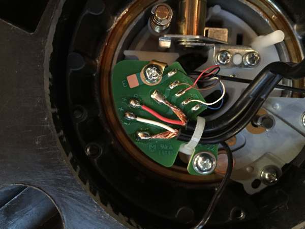
An SL-1200 is super-simple to mod. Here's a photo of the arm base with stock RCA cables. The RCA cables get replaced with shielded twisted pair. The STP shields tie to point "E"; the ""-" signal leads tie to the points where the RCA's shields originally connected.
https://ka-electronics.com/shop/index.php?route=product/category&path=66
Most of my boards go to mastering facilities who cut vinyl. The primary playback turntable is the lathe itself: The RAW preamp output is usually RIAA-EQ'd in analog and is used for acetate and test pressing QC. I also provide a large number for restoration/transfer or consumer use where RIAA EQ is applied in DSP.
To put it simply almost all carts are floating generators. Whether the interconnection is balanced depends on how it is terminated.
Some MM carts have an internal link which ground one channel's "-" connection to an internal shield. Others have a removable link. I have an AT which is like the former and Stantons like the later which have external links. Internally-grounded shields do imbalance one channel, usually the right, somewhat slightly.
Here's a diagram I originally provided for Lathe Trolls which shows several shield connection options depending on the turntable and cart case ground. Ideally the shield(s) telescope all the way from the male XLR back to the wand and headshell with the TT frame ground separate leading back to a the preamp case ground. The telescoped shields, which drop off at the TT, carry no current unless they are linked.
An SL-1200 is super-simple to mod. Here's a photo of the arm base with stock RCA cables. The RCA cables get replaced with shielded twisted pair. The STP shields tie to point "E"; the ""-" signal leads tie to the points where the RCA's shields originally connected.
https://ka-electronics.com/shop/index.php?route=product/category&path=66
Concerning Proteus, you can either ask Jan Didden for the single article https://linearaudio.net/ for $2.90, or all volumes on a stick for $99 from this forum's shop https://diyaudiostore.com/collections/books/products/the-complete-linear-audio-library or in Europe from https://www.elektormagazine.com/news/complete-linear-audio-library for Euro89.95.Sounds great, you have circuit diagram to share, link, measurements?
If you just want the article, this is the one you need https://www.linearaudio.net/proteus-current-input-moving-coil-preamp
Craig
Last edited:
- Home
- Source & Line
- Analogue Source
- Fully balanced MC phono preamplifier thoughts