Thanks! I feel like I am nearly back to where I was before just in a different way. I don't have it right yet on all material but it sounds really good on some.Looks like you are making nice progress setting up to new room. I always have to go back to basics too, whenever getting serious about matching to a room.
Crossovers are something I am thinking about so that is a useful reminder. I haven't had much success using the outdoor measurement as a basis for EQ, even though it is not wildly different to the in room uncorrected response in the new room. Didn't work in the old one either.But it wasn't clear that natural roll-off is also minimum phase, and how beneficial out-of-band flattening is to implementing crossovers.
I'm in the 15dB boost area correcting these which is something I want to reduce when the subs are built, it will be interesting to see if it results in much difference, reducing the opportunity for modulation distortion can't be a bad thing.boost is my threshold of OK. If more than 6db shows on the transfer, i know I have to move xover deeper into the passband, or increase xover order.
And what I really really like, is because of the 'pre-flattening' I can change the crossover freq, type, order, without doing anything else...no revisiting driver EQ etc. Easy peasy 😀
I know you probably have all this down...thought it might be helpful to others ...
Flattening the magnitude response through DRC is fairly simple and doing that on both arrays and subs before adding a textbook crossover might prove to be the best way to do it. I have to decide what measurements I will use to base the crossover on. Outdoor measurements or more highly averaged in room.
Well using your name drew your attention so it worked 😉I'm going to have to subscribe to this thread if you guys are taking my name in vain. Almost missed the discussion; taking time away from speakers to do some landscaping.
140 Hz is too low to absorb with reasonable thickness. I would either put the arrays right on an absorber which is right on the wall or pull the arrays out far enough so null moves into sub territory.
The current position has the front of the arrays 50cm from the front wall, with the cabinet depth and the absorbers I plan to build being 180mm thick the absorber will be against the wall with the speaker right up against it. Whether it will work or not is still to be seen but 140Hz is a lot easier to absorb than 60Hz.
Porous absorber calculator gives me a rating of 0.3 at 140Hz, so less than ideal but not hopeless to reduce the impact.
I can't pull them out far enough to avoid the nulls or my nose will be touching them which presents a bit of a comb filtering issue 🙂
A Horbach-keele crossover at 80 to 90Hz could avoid the worst of the nulls in the arrays, but it remains to be seen if the subs can be placed in any practical position to have them free of the nulls below that. Or if some form of blended lower slope arrangement will work better.
Porous absorber calculator is my friend too. It tells you some of that depth can be airspace. If you use the multilayer absorber calculator on same website, you might find improvement with a limp membrane sandwiched between layers of fiberglass, depending on frequencies you want to cover and density of available membranes.
I was in too much of hurry yesterday to appreciate your earlier comments of indoor averaged measurement coming close to outdoor. My arrays have never been outdoors so I don't have similar experience. I have to try and quantify agreement with Vituix simulation based on single driver measurements and see how close it really is. Visually it looks in the ballpark, which is all I've ever asked of simulation.
I'm in the same squeeze as you. I'm trying to listen so far from the arrays to minimize combing that I have issues with reflections off the back wall.
Why H-K? Don't understand how that helps given that it comes from expanding array type of design. But do have vague recollection that it allows weighting vs frequency of both sources to achieve desired response curve.
Hey, fluid:
Good to see you back at it. I've been tweaking my customized DRC scheme a bit lately; any chance you wouldn't mind sending me an mdat file with a single point (listening position) measurement of each speaker and auditioning a filter or two for me? No worries either way 🙂. Eventually I'll update the files on the convolution thread...
Good to see you back at it. I've been tweaking my customized DRC scheme a bit lately; any chance you wouldn't mind sending me an mdat file with a single point (listening position) measurement of each speaker and auditioning a filter or two for me? No worries either way 🙂. Eventually I'll update the files on the convolution thread...
I will post some graphs from simulation later but it has a gentle rolloff on the highpass side before it rolls off steeply which means the arrays will put out nothing below 80Hz which could help me to avoid the lower nulls. The low pass side covers a wider range which isn't too much of an issue for the subs I have in the works as the drivers have a fairly extended range. I did a virtual test with a 24dB Linkwitz at 80Hz and it increased the dip at 140Hz quite a lot.Why H-K? Don't understand how that helps given that it comes from expanding array type of design. But do have vague recollection that it allows weighting vs frequency of both sources to achieve desired response curve.
Happy to try them out for you although they may not work as well on arrays as they do for more conventional speakers. If you can send me through the drc files I can easily make a filter to compare. Single point measurements are not working well for me so I would run it on a vector average as I am at the moment.Hey, fluid:
Good to see you back at it. I've been tweaking my customized DRC scheme a bit lately; any chance you wouldn't mind sending me an mdat file with a single point (listening position) measurement of each speaker and auditioning a filter or two for me? No worries either way 🙂. Eventually I'll update the files on the convolution thread...
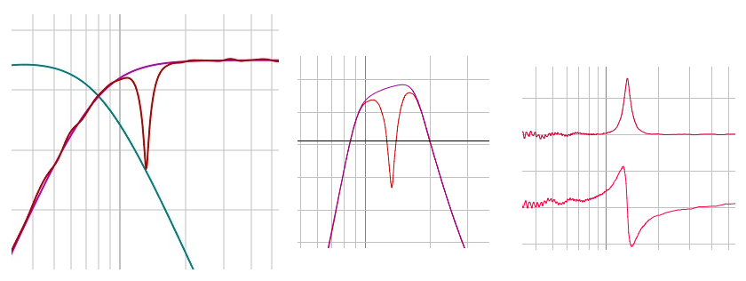
Here are some graphs of two different crossover topologies that I have tried by virtually combining impulses in REW.
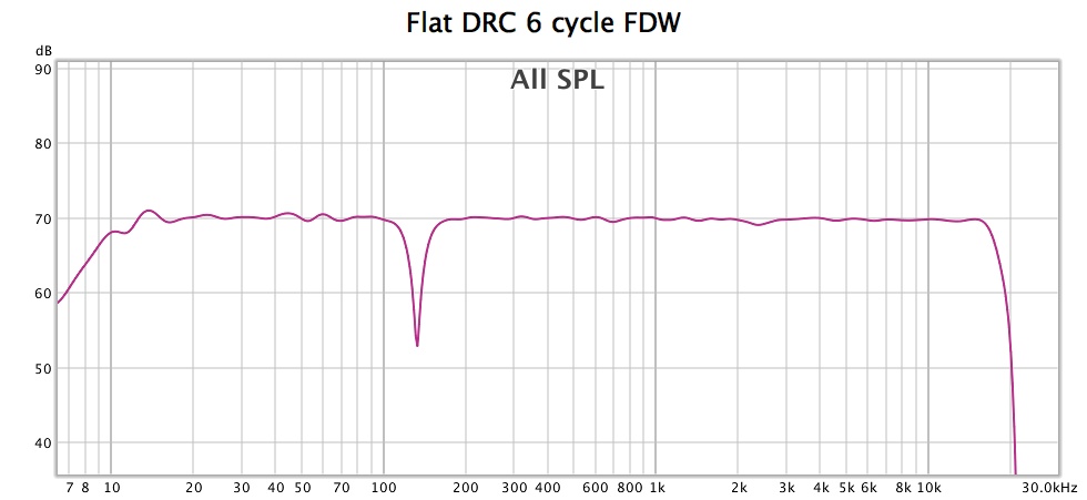
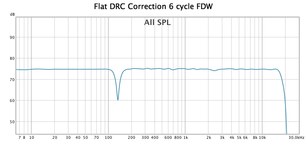
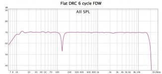
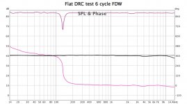
I have started off with a Flat DRC correction shown with a 6 cycle FDW as that is the closest to how the correction was aimed for and also it allows easier comparison of the graphs. This is the baseline measurement. This shows the 140Hz dip I am getting from the front wall.
I am using perfect impulses from Rephase to simulate the sub and crossover slopes. The corrected impulse has the IR centre exactly at 0 to avoid and timing induced errors.
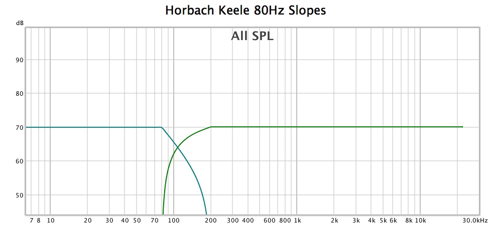
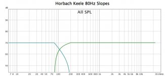
These are the Horbach Keele filter slopes for an 80Hz crossover
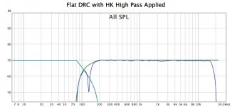
This is the Flat correction with the HighPass applied, low pass also shown
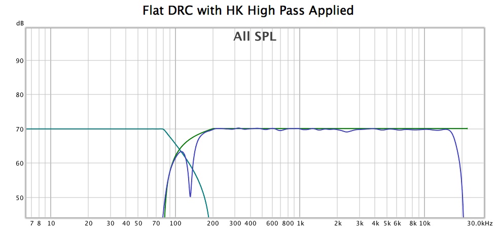
This is the combined result, showing very good integration of acoustic slopes to the ideal ones.
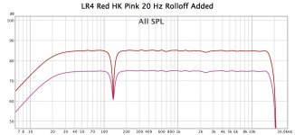
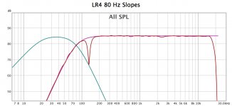
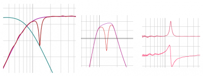
I tried a more standard LR4 linear phase at 80Hz, this graph shows the targets and Flat correction with High Pass added
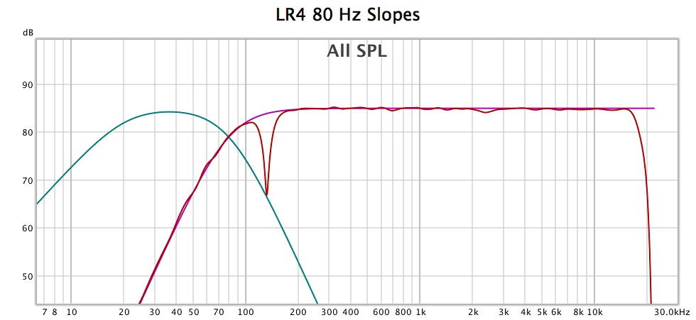
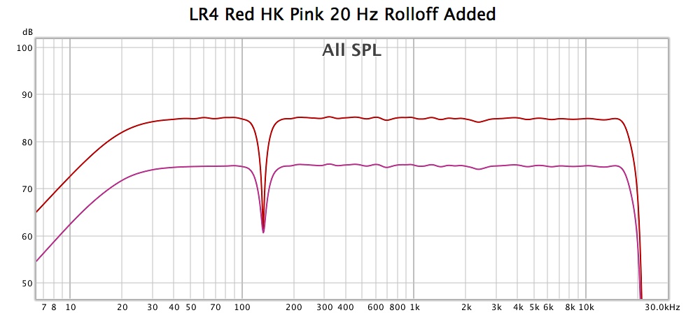
This graph shows the difference between the two with a 20Hz second order rolloff added, very similar apart from the fact that the 140Hz dip has been made quite a bit deeper 😱 More experimentation needed with slopes and frequencies to see if the dip can be left as it is in the baseline with more standard crossover types.
I have started off with a Flat DRC correction shown with a 6 cycle FDW as that is the closest to how the correction was aimed for and also it allows easier comparison of the graphs. This is the baseline measurement. This shows the 140Hz dip I am getting from the front wall.
I am using perfect impulses from Rephase to simulate the sub and crossover slopes. The corrected impulse has the IR centre exactly at 0 to avoid and timing induced errors.
These are the Horbach Keele filter slopes for an 80Hz crossover
This is the Flat correction with the HighPass applied, low pass also shown
This is the combined result, showing very good integration of acoustic slopes to the ideal ones.
I tried a more standard LR4 linear phase at 80Hz, this graph shows the targets and Flat correction with High Pass added
This graph shows the difference between the two with a 20Hz second order rolloff added, very similar apart from the fact that the 140Hz dip has been made quite a bit deeper 😱 More experimentation needed with slopes and frequencies to see if the dip can be left as it is in the baseline with more standard crossover types.
Attachments

There isn't much withholding you from using some EQ on the subwoofer side (on top of that crossover) at the problem frequency of the arrays. Just don't use too high of a Q and limit the amount of boost. Should work well to balance out the dip. Maybe it works even better if you remove energy at that dip from the arrays. Check the processing (FIR file) to see if there's a peak in the processing at that 140 Hz frequency. As it is a null, more energy there leads to a bigger problem, so creating a mild EQ dip on the arrays while creating a similar peak on the sub side might work well to lessen the total effect of that dip.
That's what I do with the left/right arrays in my room due to not having symmetric loading. Way less EQ is needed than one would expect, just try it.
Something like this works if the dip is consistent over a larger area, as this is an average that should be the case. As long as the sub has an even FR output over that same frequency area.
Last edited:
Your 80 Hz XOs LPFs are down over 10 db by 140 Hz, limiting how much the sub can help fill in that dip, as Wesayso commented. You will get some marginal benefit from raising the XO. I'm using 100 Hz with no sub-localizability issues.
But even the .3 loss factor on the boundary interference you mentioned may be enough to reduce the depth of the null so that you have enough headroom to equalize it away.
But even the .3 loss factor on the boundary interference you mentioned may be enough to reduce the depth of the null so that you have enough headroom to equalize it away.
Interesting points, a combination of acoustic treatment, crossover frequency, slope and reduction in level in the main speakers should help to make it much better.
All depends on what sort of response I can get from the subs in room.
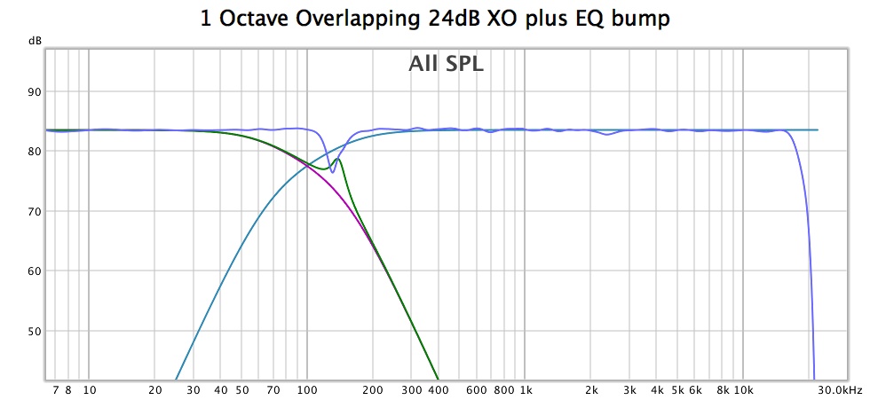
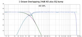
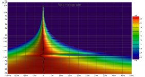
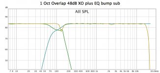
This shows an overlapping 1 octave 24dB slope crossover at 100Hz with an EQ bump in the sub, it has definitely helped as the null in the spectrogram has been pushed out in time. EQing on the sub side is a bit trial and error as the shape has to be different than filling the gap in the overall curve.
The 1 Octave overlapping at 48dB could be interesting as it has similar shape in the top of the crossover before dropping more rapidly afterwards. I will simulate that when I free up some measurement slots in REW, sometimes 30 is not enough for this sort of virtual testing 🙂

All depends on what sort of response I can get from the subs in room.
This shows an overlapping 1 octave 24dB slope crossover at 100Hz with an EQ bump in the sub, it has definitely helped as the null in the spectrogram has been pushed out in time. EQing on the sub side is a bit trial and error as the shape has to be different than filling the gap in the overall curve.
The 1 Octave overlapping at 48dB could be interesting as it has similar shape in the top of the crossover before dropping more rapidly afterwards. I will simulate that when I free up some measurement slots in REW, sometimes 30 is not enough for this sort of virtual testing 🙂
Attachments
1 Octave 48dB Crossover with EQ bump in sub channel, pretty much the same spl response around crossover much steeper outside that band.

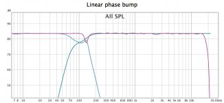
This the linear phase version with a different EQ shape from rephase, looks better on an spl plot but the spectrogram is the same but with more going on before the peak from the linear phase EQ
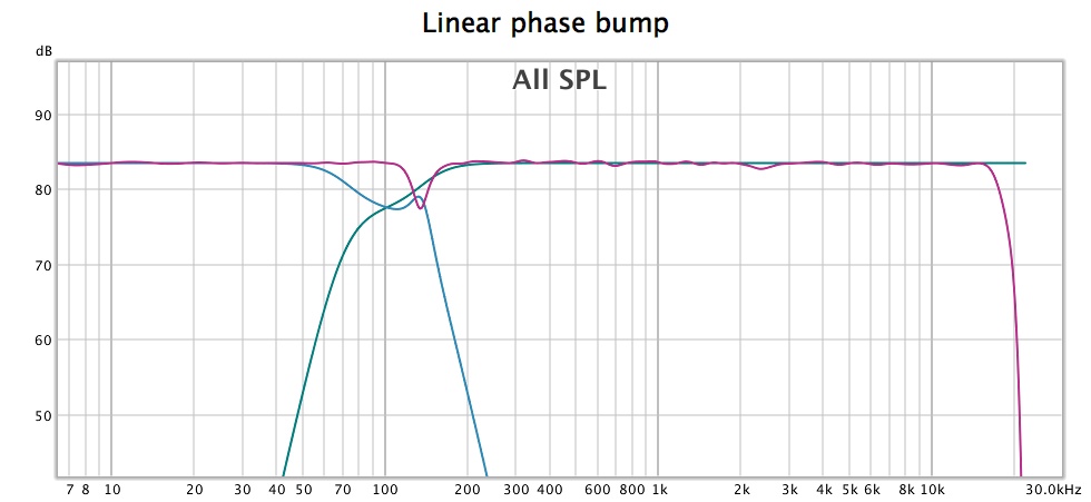
This the linear phase version with a different EQ shape from rephase, looks better on an spl plot but the spectrogram is the same but with more going on before the peak from the linear phase EQ
Attachments
This is a RePhase exercise right? Not a real null in the mains, just a virtual one done by EQ, right?
Not shure but could imagine phase of that dip maybe can be a little wild, what i mean is its not pure linear phase and not pure minimum phase but a mix of both, guess a chance to repair that then into REW you need to divide a carefull alligned measured line array IR with textbook target of a carefull alligned target curve IR, to ignore HF stopband from measured IR then filter the two IR before the divide command for example 1/1 at 125Hz and export that as frd file, then over in Rephase use whatever mix of minimum phase and linear phase filters it takes to get that hump flat as pancake in both the amplitude and phase domain, below should be some pointers 😛
Attachments
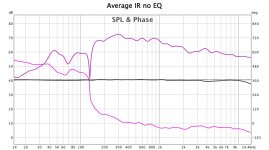
No the null is real, it appears in the averaged measurement and DRC does not try and correct it.This is a RePhase exercise right? Not a real null in the mains, just a virtual one done by EQ, right?
These images show it, 6 cycle FDW to clean up the phase and unwrapped to see the cliff more clearly. The exercise part is combing the real corrected measurement with pure impulses to represent a perfect sub.
I'll have to read that one a few times to understand it 🙂 I don't think it can be corrected electrically, but needs a combination of absorption and mitigating with the sub channel if possible. I have had no success with dividing impulses before, it always sounds wrong somehow.below should be some pointers 😛
Attachments
Some progress has been made in the physical world 🙂
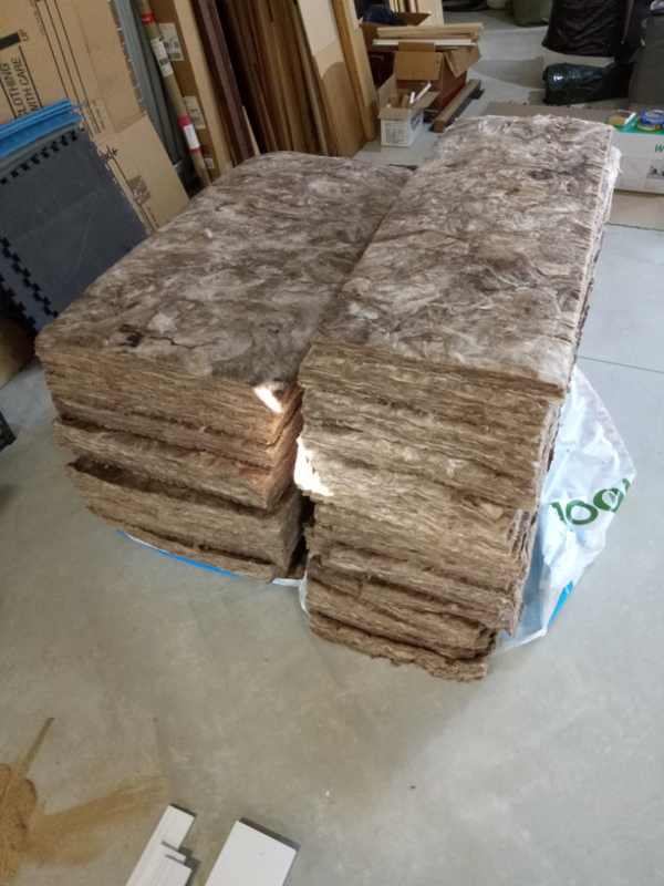
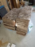
Pile of Glass fibre batts
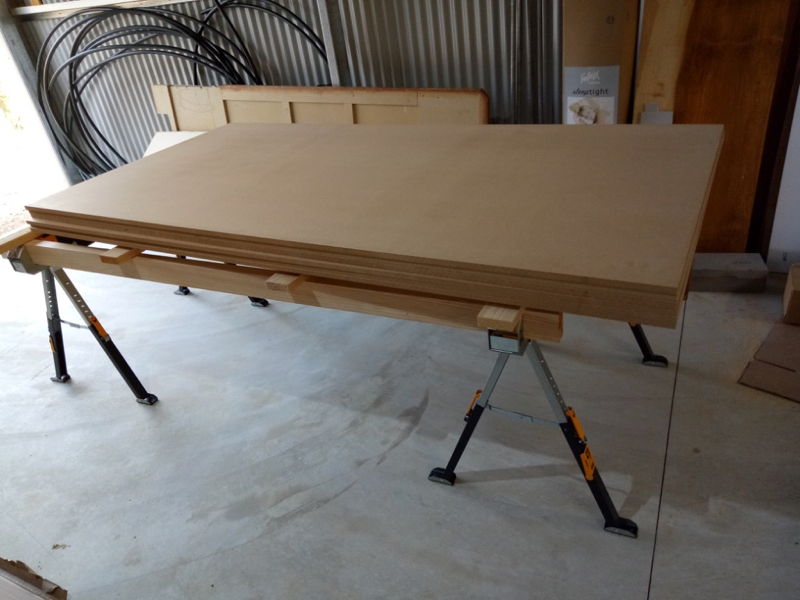
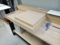
Pile of MDF
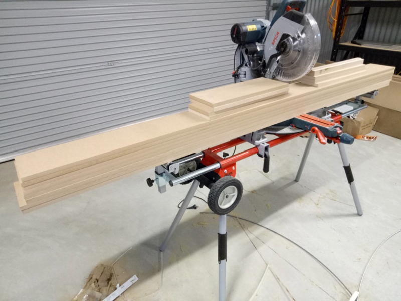
MDF cut for sub cabinets and absorber frames

Pile of Glass fibre batts
Pile of MDF
MDF cut for sub cabinets and absorber frames
Attachments


Big plans! 😀
I should end with 3 panels 560 x 2260 x 180 (whd) and 5 panels 430 x 2260 x 150
That's what I got out of two bags of glass fibre and three sheets of MDF
Roughly 500 x 500 boxes for the 15" drivers, reasonable compromise between size and efficiencyplans for big subs?
The original idea was for corner traps and first reflection control. Having measured, the ETC shows less early reflections than I thought but a few bass nulls, so I will try to see if I can reduce the front wall null enough to be dealt with by other means.
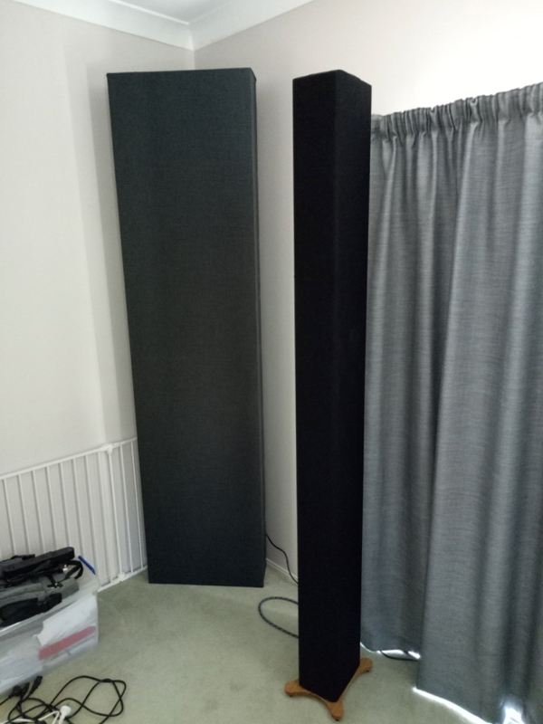
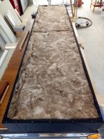
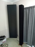
Here are some progress shots of the absorbent panels, one completed so far 🙂
Basic frame with backing fabric attached (excuse the perspective the divider is in the middle of the frame)
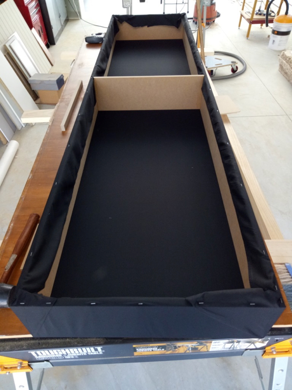
Filled with fibreglass insulation

Front fabric attached
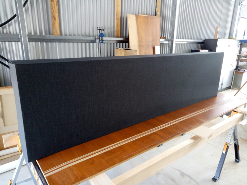
In room next to array for scale, even with no bracing these things are awkward to move around.
Basic frame with backing fabric attached (excuse the perspective the divider is in the middle of the frame)
Filled with fibreglass insulation
Front fabric attached
In room next to array for scale, even with no bracing these things are awkward to move around.
Attachments


- Home
- Loudspeakers
- Full Range
- Full Range TC9 Line Array CNC Cabinet