Mark floated the excellent idea of a discrete design, which we ignored completely.
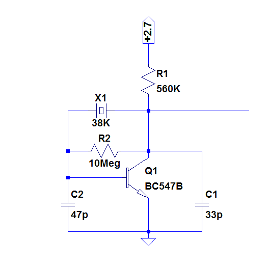
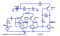
Looking at your table, I had a kind of epiphany: a symetrical, complementary design was bound to have a hefty, difficult to reduce current consumption, meaning single-ended was the logical way to go, and I came up with this practical, tested design.
>I'm surprized you have a 38 kHz quartz ...
As I am a hoarder, I have a large stock of everything, some were even bought when I was a teenager.
I have crystals of all common frequencies, plus many other, but I could have made the test with a 32.7K one.
> Looking at your design : R2 130Mohm ? Transistor can be a BC84x one ?
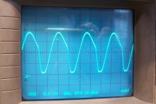
Oscilloscope pic is with a 1:10 probe , I hope ? A ST gate will clean that up , not that I expect much better from a 4069UB output.
The initial values, including the ~130 Meg resistor were the raw results from "back of an envelope calculations".
Although they worked, they aren't optimal: the resistor can be much smaller, in fact 2.2 Meg still works.
10Meg is probably reasonable.
The probe is indeed a 1/10, and has 12pF capacitance. In fact, without the probe the oscillator stops.
C1 should thus be increased to ~33pF (although the subsequent gate will also have some capacitance).
The waveform is typical of a linear oscillator, but it is somewhat improved with a lower bias resistor (better duty-cycle).
I opted for a 2N3904, because I feared the higher feedback capacitance of a BCxyz would make the oscillation more difficult, but this fear is probably unfounded.
I'll test other types tomorrow.
A ST-input gate will be necessary at the output, otherwise you will be confronted with the same cross-conduction issues that plagued your previous attempts and made the current consumption unbearable.
You will need a way to be able to shut down the downstream circuitry whilst keeping the oscillator alive (it is slow-starting, obviously), unless you can keep everything permanently supplied, which would be the simplest option.
Looking at your table, I had a kind of epiphany: a symetrical, complementary design was bound to have a hefty, difficult to reduce current consumption, meaning single-ended was the logical way to go, and I came up with this practical, tested design.
>I'm surprized you have a 38 kHz quartz ...
As I am a hoarder, I have a large stock of everything, some were even bought when I was a teenager.
I have crystals of all common frequencies, plus many other, but I could have made the test with a 32.7K one.
> Looking at your design : R2 130Mohm ? Transistor can be a BC84x one ?
Oscilloscope pic is with a 1:10 probe , I hope ? A ST gate will clean that up , not that I expect much better from a 4069UB output.
The initial values, including the ~130 Meg resistor were the raw results from "back of an envelope calculations".
Although they worked, they aren't optimal: the resistor can be much smaller, in fact 2.2 Meg still works.
10Meg is probably reasonable.
The probe is indeed a 1/10, and has 12pF capacitance. In fact, without the probe the oscillator stops.
C1 should thus be increased to ~33pF (although the subsequent gate will also have some capacitance).
The waveform is typical of a linear oscillator, but it is somewhat improved with a lower bias resistor (better duty-cycle).
I opted for a 2N3904, because I feared the higher feedback capacitance of a BCxyz would make the oscillation more difficult, but this fear is probably unfounded.
I'll test other types tomorrow.
A ST-input gate will be necessary at the output, otherwise you will be confronted with the same cross-conduction issues that plagued your previous attempts and made the current consumption unbearable.
You will need a way to be able to shut down the downstream circuitry whilst keeping the oscillator alive (it is slow-starting, obviously), unless you can keep everything permanently supplied, which would be the simplest option.
I hadn't ignored Mark's idea , but discrete was not something I could do.
I was thinking more like 4007 kind of discrete , but like the Elektor pic shows , it is not that good , and I don't have an 4007 .
You build it with an 130M R ? I didn't even know they exist , but then I see at Mouser up to 10Tohms , uhm what ?? Yes Terra ! That is insane . A PCB is never going to be that clean .
Now don't go putting too much time in this Elvee. I'm pretty sure your LC oscillator as an on/off one will win.
Attachments
As shown, the 4007 is used just like a 4069, and will suffer the same ills.
It would be necessary to use the individual transistors in a non-complementary configuration, but I don't think it is worth the trouble.
I have tested an updated version of the BJT oscillator:
This is the waveform, measured with an active probe having a capacitance <1pF:
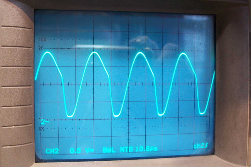
The amplitude is a bit smaller than with the 2N3904, but it remains acceptable.
A thorny problem now remains: the output wave-shaping.
That has to be done with a schmitt trigger, but with the input spending a lot of time in the mid-supply region, I feared that the consumption would go up, and I was right unfortunately.
I tested a single operator of a 74HC14 at 3V Vdd: the consumption was 80µA.
With a 74HC132, it was also 80µA, but I hoped that disabling it using the other input would halt the consumption, but nope: it was reduced to 75µA.
A 74AC14 required 720µA, but a 74HCT14 only needed 26µA.
To benefit from the micropower properties of the oscillator, you would need a matching shaper, which is certainly not impossible but would be relatively complicated.
Therefore, your best option remains the LC oscillator
It would be necessary to use the individual transistors in a non-complementary configuration, but I don't think it is worth the trouble.
I have tested an updated version of the BJT oscillator:
This is the waveform, measured with an active probe having a capacitance <1pF:
The amplitude is a bit smaller than with the 2N3904, but it remains acceptable.
A thorny problem now remains: the output wave-shaping.
That has to be done with a schmitt trigger, but with the input spending a lot of time in the mid-supply region, I feared that the consumption would go up, and I was right unfortunately.
I tested a single operator of a 74HC14 at 3V Vdd: the consumption was 80µA.
With a 74HC132, it was also 80µA, but I hoped that disabling it using the other input would halt the consumption, but nope: it was reduced to 75µA.
A 74AC14 required 720µA, but a 74HCT14 only needed 26µA.
To benefit from the micropower properties of the oscillator, you would need a matching shaper, which is certainly not impossible but would be relatively complicated.
Therefore, your best option remains the LC oscillator
Attachments
If the second line from below is the 0V , then yes it spends most of the time in the higher current zone and looking at the 2 ST thresholds of AUP and AHC, the duty cycle will be very asymetric.
I may try it though . I have BC846B and BC849C and even a 15 Mohm 0805.
Thanks Elvee !
I may try it though . I have BC846B and BC849C and even a 15 Mohm 0805.
Thanks Elvee !
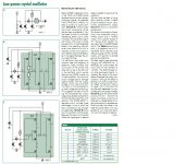
Here is a quick-and-dirty attempt to "build a CD4069UB out of BJTs instead of MOSFETs".
Works pretty well, draws ~ 4.8uA in steady state, might be a useful starting point for a more serious effort (?)
_
Works pretty well, draws ~ 4.8uA in steady state, might be a useful starting point for a more serious effort (?)
_
Attachments
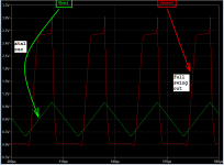
With the ICs I tested, the final duty-cycle was mildly asymetrical.If the second line from below is the 0V , then yes it spends most of the time in the higher current zone and looking at the 2 ST thresholds of AUP and AHC, the duty cycle will be very asymetric.
I may try it though . I have BC846B and BC849C and even a 15 Mohm 0805.
Thanks Elvee !
15Meg is perfectly OK: the oscillator is extremely tolerant regarding that resistor
It looks fine, but as I remarked earlier, a µ-power shaper would be relatively complicated: 6 transistors to shape the waveform of an ultra-basic 1-transistor oscillator is acceptable if you really need it and have no other viable solution, but otherwise it isn't the most attractive option.Here is a quick-and-dirty attempt to "build a CD4069UB out of BJTs instead of MOSFETs".
Works pretty well, draws ~ 4.8uA in steady state, might be a useful starting point for a more serious effort (?)
_
Using the 4007 individual transistors would be an option, as they come in a single package, and biasing them individually could overcome the threshold voltage problem limiting them to a 3V supply (BTW, does a 74HC4007 version exists?), but it would remain relatively complicated, especially so because of the internal connections: in particular, the N and P gates are connected together for the three operators, which is a serious headache.
An analog switch like the 4016 could interface an always-on oscillator with the rest of the momentarily on circuit: the supply connected to the permanent 3V, and the control to the downstream circuitry.
That's one more chip, of course, and under-utilized as well. Not very attractive either.
Here is a quick-and-dirty attempt to "build a CD4069UB out of BJTs instead of MOSFETs".
Works pretty well, draws ~ 4.8uA in steady state, might be a useful starting point for a more serious effort (?)_
Yes 6 transistors is a bit much for my project here , but it can be useful for others.
A micro power opamp with ST could do the same.
With Elvee's LC on/off one , I can get the whole job done with 2 little logic gates , and a third for the ~ 250usec start delay. 99.99% of the time it will consume 1uA or so , as remotes are dormant most of the time.
Maybe you will design a circuit for me one day and give me the opportunity to say no thanks. It would be symmetric. Good luck in your hobby!
Sorry you felt it as a rejection , Mark , that was not my intention. I wanted to keep it simple , like I said , 13 components for what can be done by a micro power opamp at this relative low frequency is a bit much.
I would love to design a circuit for you , but I think you have far more knowledge and means than I will ever have.
I would love to design a circuit for you , but I think you have far more knowledge and means than I will ever have.
Cell phone battery from old phone?
They give large current when needed, and you will get as scrap.
Compact too.
They give large current when needed, and you will get as scrap.
Compact too.
^ That is not a bad idea , Nareshbrd ! My old samsung 2G phone has a 800mA Li , maybe half capacity left.
Old faithful 4069 UB can be used although with rechargeble battery , current consumption isn't that important , but it will need a switch off at low voltage , and will need to take it out to charge in the phone. It is conveniently small , better than 2 AAA's. Connection isn't as good as AAA's or directly solder it , and with a 3pin connector to the phone for charging.
The 3,7 -3 V of Li will allow 2 IR-LED's in series , so less peak current needed.
It will take more to change an existing remote that comes with a 2 AAA holder to one with a Li bat , and when that battery dies , it may be hard to find another that fits. Whereas AAA are all the same size.
Nokia BL-5
Classic, and about $2 here.
Actually, with smartphones the trend is to have directly soldered ones, an effort to make them more compact. Now they are inside, there is no way a user can change it.
Here we get pocket FM radios that play flash drive / SD card as well, charge off cell phone chargers, and use cell phone batteries.
There are charging chips available for that purpose, or simply put a drop resistor in series, and use an ordinary round socket, or whatever is convenient, from a charger which is handy.
Possibly you have old cell phone chargers lying around, can be used here.
You can use a 3.6V pack intended for cordless phones, those are pretty common, and no issue with changing, those mostly come with a connector.
Last edited:
Lithium batteries tend to catch fire when they are charged to a too high voltage, and the voltage of a USB power supply is too high. You can charge NiMH batteries with a simple power supply and series resistor, but not lithium batteries.
Phone chargers only give a voltage , the actual charger that regulates the voltages and currents are in the phone or mp3 player or camera ,... and must be precise . Using special chips for charging Li batt's is too much .
- Home
- General Interest
- Everything Else
- Frequent on/off switching of quartz crystal oscillator