Thanks Elvee for all your time and testing. It certainly seems like a good option for a on/off oscillator . Any idea how many cycles before frequency and amplitude are right ?
What a surprise that the HCU04 takes more current than the HC04. (and so much more than the 4069UB !)
I have a 68uH inductor for a buck converter and a HC1G00, will it work with around 470nF , goinig the other way than going from 33nF 1 mH to 10mH and 3,3 nF ?
What a surprise that the HCU04 takes more current than the HC04. (and so much more than the 4069UB !)
I have a 68uH inductor for a buck converter and a HC1G00, will it work with around 470nF , goinig the other way than going from 33nF 1 mH to 10mH and 3,3 nF ?
Elvee, you can experiment with installing "dropping resistors" in series between the supply pin of the hex inverter IC, and the power supply rail with its bypass caps. These resistors will reduce the total supply voltage applied to the inverters, reducing shoot-thru current (a/k/a crowbar current) when an inverter input transitions through the "both transistors are ON" zone about halfway between Vdd and Vss. You may also want a bypass cap, especially with the modern silicon gate "buffered" logic families.
Now the oscillator's supply current flows through the dropping resistor, which reduces the oscillator's supply voltage ... which reduces its supply current ... which increases its supply voltage ... until an equilibrium is reached. And the final current is lower than previous designs using Rdropper = zero ohms. Or so we expect.
You could even contemplate connecting a PNP or PMOS switch across the dropping resistor, as a sort of turbocharged mode, to get snappier edge rates and less jitter. Low power mode = switch off ; turbo mode = switch on.
_
Last edited:
No, I didn't make an oriented, deterministic test for that so far, but since the breadboard setup is still intact upstairs, I can do it easily tomorrow.Thanks Elvee for all your time and testing. It certainly seems like a good option for a on/off oscillator . Any idea how many cycles before frequency and amplitude are right ?
When I made the tests, it appears (subjectively) to start instantly, and for a normal human being, this would be <100ms.
More than a 4069UB is not a surprise: the conductance of the MOSFETs is higher, and their threshold voltage is lower.What a surprise that the HCU04 takes more current than the HC04. (and so much more than the 4069UB !)
The HC04 is counter-intuitive, but I think that with the buffered gates and their higher gain, they spend a smaller proportion of their time near mid-supply, where the consumption is highest, lowering the average consumption
The Thomson formula principle is a good base, but it shouldn't be pushed too far: the pivotal impedance of an LC circuit is √L/C, and it shouldn't stray too far from the general impedance level of the active device(s); 68µH/470nF is 12 ohm, and modern logic families can make them sing, but at the cost of an increased consumption and lower Q (thus, less stability).I have a 68uH inductor for a buck converter and a HC1G00, will it work with around 470nF , goinig the other way than going from 33nF 1 mH to 10mH and 3,3 nF ?
I have plugged a 1mH and two 33nF in the last configuration (the 74HC04), and it oscillated like a charm, at the correct frequency. The only difference was the current consumption increased to 450µA: a three-fold increase.
Note that for all the later tests, I didn't try to optimize the 27K resistor value: ideally, it should be suited to the rest of the circuit, tank and IC.
The components themselves are no-brainer choices: I simply opted for two equal capacitors, but in reality a CMOS gate has a quasi-infinite power gain thanks to its quasi-infinite input impedance, and it would make sense to use highly asymetrical values for a better match.
In short, there is a lot of room for improvement, in stability, current consumption, etc. but the arbitrary values I picked already seem to work rather well.
If you want me to test a particular setup (type of gate, etc.), you can ask me, but I'll test DIP only circuits.
If a single operator of the package is used, it might work (but I have some doubts)Elvee, you can experiment with installing "dropping resistors" in series between the supply pin of the hex inverter IC, and the power supply rail with its bypass caps. These resistors will reduce the total supply voltage applied to the inverters, reducing shoot-thru current (a/k/a crowbar current) when an inverter input transitions through the "both transistors are ON" zone about halfway between Vdd and Vss. You may also want a bypass cap, especially with the modern silicon gate "buffered" logic families.
If other operators are also used, it will have a disastrous effect.
With a CD4007, it would be possible to isolate the supply of a single pair, and it might be usable.
A series resistor in the supply will certainly reduce the current drain, but it might also impair the startup, when the consumption is at its highest.Now the oscillator's supply current flows through the dropping resistor, which reduces the oscillator's supply voltage ... which reduces its supply current ... which increases its supply voltage ... until an equilibrium is reached. And the final current is lower than previous designs using Rdropper = zero ohms. Or so we expect.
That is certainly a test I can easily make.
It sounds like a complicated propositionYou could even contemplate connecting a PNP or PMOS switch across the dropping resistor, as a sort of turbocharged mode, to get snappier edge rates and less jitter. Low power mode = switch off ; turbo mode = switch on.
_
At those times RickTH would have gated his RC oscillator off, go into low power mode with the crystal oscillator still running but at minimum power. This means there are no five thousand cycle startup delays -- it's always on. At those times RickTH would have gated his RC oscillator on, go into high power mode (short out the dropping resistor) and accept higher current consumption (15 uA !!) in exchange for fast edge rates and reduced jitter.
OK, I see what you mean: a keep-alive circuit allowing a quicker start.
Let's see what Rick's opinion is
Let's see what Rick's opinion is
Well the reasons/questions I started this thread for , have been answered.
I wanted a simple solid stable quartz oscillator (against a changing supply voltage) , but had a suspicion that on/off switching could be a problem. You guys set me straight on that.
I have the choice of a very low power constant running quartz oscillator or LC , maybe with Marks idea of limiting switching current and a "turbo" when a button is pressed , or just the quicker starter LC oscillator only running when a button of the remote is pressed and where the current draw is not a big issue .
It will depend on getting as low powered as posible with still getting fast edges from AHC1GU or AUP1GU I intend to buy. They should be better than the 74AC or HCU or HC , Elvee tested. 74AC is known for noice and ground bounce. 4069UB would have been ok , but using it far below the recommended minimum 3V seems bad designing.
Thanks guys !
>It will depend on getting as low powered as posible with still getting fast edges from AHC1GU or AUP1GU I intend to buy.
They should pose no problem: their specs are very similar to a HCU device, somewhat faster.
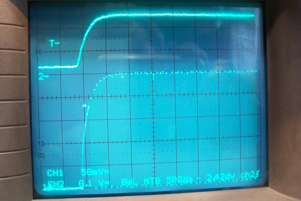
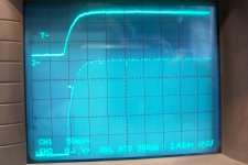
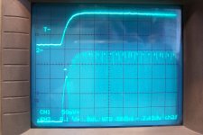
I have measured the startup time for the three 74xxx at 2.5V Vdd (worst case).
Top trace is the supply voltage, bottom is the unbuffered output.
First, the HC04:
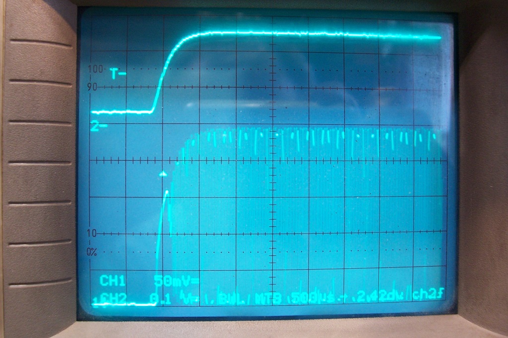
Next, the HCU04:
Then the AC04:
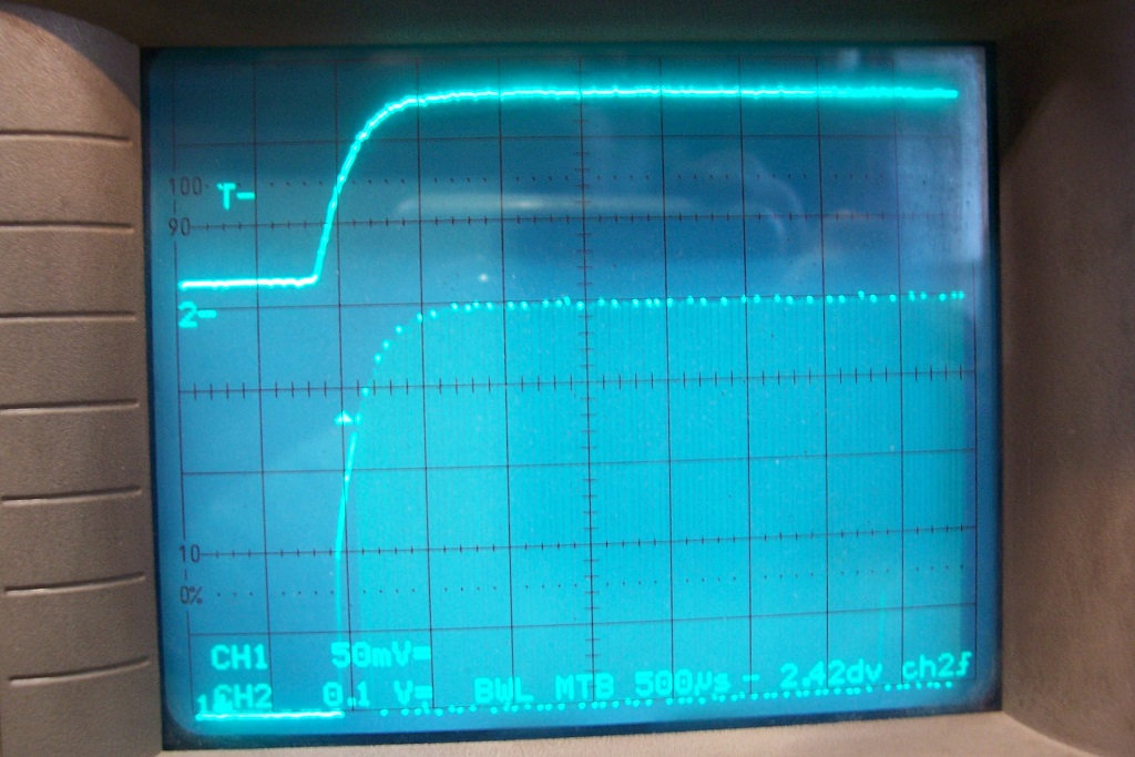
Thus, around 250µs for all three
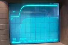
The AC04 with the 2x33nF + 1mH inductor:
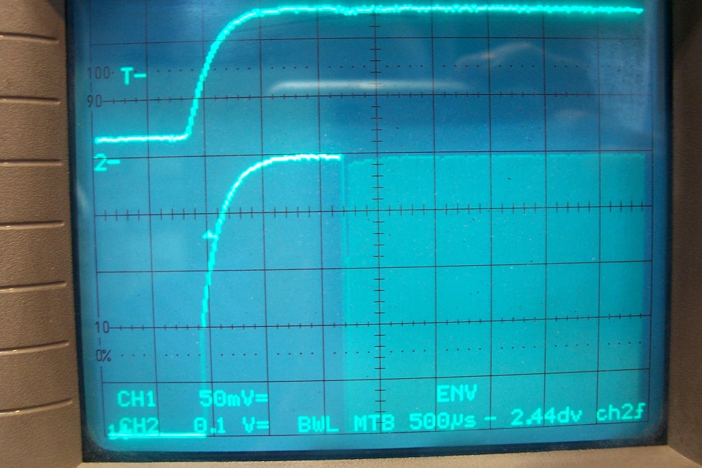
This time, it is increased to ~1.5ms.
Note that the small oddities on the signal are the result of artifacts generated by the scope being in digital mode. On the last pic, I activated the envelope mode to clean up the waveform.
I also tested the idea of heavily asymetrical capacitors (for the AC04, but it would work for the others too): 1.8nF (input side) and 20nF (output side).
Nothing changed, except the stability between 2.5V and 3V became better than 1Hz. Probably on a par with a ceramic resonator, if not better.
I also tested a 74HC00, and it worked exactly like a 74HC04.
Consumption at 2.5V is 50µA and 104µA at 3V.
Finally, I tested Mark's idea of a resistor to reduce the shoot-through spike.
With the HCU04, I tried up to 150ohm: with this value, nasty artifacts already begin to appear on the transition, and the consumption at 2.5V was only reduced from 395µA to 325µA.

Unsurprisingly, other families were a complete mess with the resistor present.
They should pose no problem: their specs are very similar to a HCU device, somewhat faster.
I have measured the startup time for the three 74xxx at 2.5V Vdd (worst case).
Top trace is the supply voltage, bottom is the unbuffered output.
First, the HC04:
Next, the HCU04:
Then the AC04:
Thus, around 250µs for all three
The AC04 with the 2x33nF + 1mH inductor:
This time, it is increased to ~1.5ms.
Note that the small oddities on the signal are the result of artifacts generated by the scope being in digital mode. On the last pic, I activated the envelope mode to clean up the waveform.
I also tested the idea of heavily asymetrical capacitors (for the AC04, but it would work for the others too): 1.8nF (input side) and 20nF (output side).
Nothing changed, except the stability between 2.5V and 3V became better than 1Hz. Probably on a par with a ceramic resonator, if not better.
I also tested a 74HC00, and it worked exactly like a 74HC04.
Consumption at 2.5V is 50µA and 104µA at 3V.
Finally, I tested Mark's idea of a resistor to reduce the shoot-through spike.
With the HCU04, I tried up to 150ohm: with this value, nasty artifacts already begin to appear on the transition, and the consumption at 2.5V was only reduced from 395µA to 325µA.
Unsurprisingly, other families were a complete mess with the resistor present.
Attachments

An afterthought about the extended startup time for the 1mH/33nF case: it is not caused by a longer buildup of oscillations (as the Q is lower), but by the time-constant of the 2x33nF with the 27K resistor, about 1.8ms.
The gate cannot be biased in its linear region until the time-constant is well over, which explains the long startup.
Splitting the caps between Vdd and Vss should solve the issue, but at this level, I don't think it is necessary for Rick
The gate cannot be biased in its linear region until the time-constant is well over, which explains the long startup.
Splitting the caps between Vdd and Vss should solve the issue, but at this level, I don't think it is necessary for Rick
Wow Elvee , thanks for doing this.
A start delay of 250us is more than good enough , and consumption at 2.5V of 50µA and 104µA at 3V is good for an on/off oscillator.
Was the frequency with the asymetrical and these standard values of 1.8nF and 20nF (and 10 mH) also 38kHz ?
A start delay of 250us is more than good enough , and consumption at 2.5V of 50µA and 104µA at 3V is good for an on/off oscillator.
Was the frequency with the asymetrical and these standard values of 1.8nF and 20nF (and 10 mH) also 38kHz ?
Yes, they were calculated for 33nF/2= 16.5nF = 1.8nF in series with 20nF.
Depending on the tolerance of the inductors and the capacitors, I get between 38.2 and 39kHz, but as I said earlier, the strategy is to make one of the cap a bit too small, and add a small parallel cap to arrive at the correct frequency. Not difficult, and very stable and reliable.
Note that for a good frequency stability, the passives need to be stable. For the inductors, it is not a problem: it may seem counter-intuitive, but microchokes (resistor-like, like the ones I used) are quite good in this respect. They have an airgap ~= to the component length, making them stable regarding temperature.
They are slightly affected by conducting or magnetic materials in their vicinity, but once they are soldered in their environment, it does not vary and they remain stable.
Never use something with closed magnetic circuit, like toroids, beads, etc.
The stable dielectrics are PP, PS, PC, mica, glass, teflon, PPS and group I ceramics, typically COG, but also any other having a tempco comprised between +100ppm/°C and -200ppm/°C (P100 to N200)
Needless to say that many other LC combinations would also work: I simply picked 1mH and 10mH as a starting point, because they are nice, round values and seemed reasonable, but you could opt for 4.7mH or another value. Don't stray into extreme L/C ratios though, it will make life difficult for the oscillator
Last edited:
Not an easy or cheap component . Can't get it locally and not that much choice at Mouser :
https://www.mouser.com/Passive-Comp...?Rl=5gb4Zer7uZ1y9677gZ1yym4wmSGT&Ns=Pricing|0
https://www.mouser.com/ProductDetai...=sGAEpiMZZMv126LJFLh8yyVlOY2UZQmb8R6s3vr5vdo=
or
https://www.mouser.com/ProductDetai...GAEpiMZZMv126LJFLh8y%2B2RKwC9HhBzjlVQ2d718F0=
not this type ?
https://www.mouser.com/ProductDetai...=sGAEpiMZZMv126LJFLh8y2sy2M7n/6dxOnW9NHLF99A=
NP0/COG are not a problem.
This one is OK and costs <1$:
https://www2.mouser.com/ProductDeta...=sGAEpiMZZMv126LJFLh8yyVlOY2UZQmb8R6s3vr5vdo=
This one has a higher DC resistance, but it should still be OK:
https://www2.mouser.com/ProductDeta...GAEpiMZZMv126LJFLh8y%2B2RKwC9HhBzjlVQ2d718F0=
That one would be OK too, despite the "drum core" form factor: the magnetic circuit remains open on the outside, resulting in a large airgap:
https://www.mouser.com/ProductDetai...=sGAEpiMZZMv126LJFLh8y2sy2M7n/6dxOnW9NHLF99A=
The ones that are completely enclosed in a ferrite cylinder aren't .
This is an example of such an unsuitable type:
https://www2.mouser.com/ProductDeta...=sGAEpiMZZMv126LJFLh8y4ZZkBFjSZO5dMr0aC5pLDY=
Thanks Elvee !
You may want to check :
https://www.diyaudio.com/forums/power-supplies/373941-inrush-current-limiter-smps.html#post6804057
At your leisure , no pressure !
You may want to check :
https://www.diyaudio.com/forums/power-supplies/373941-inrush-current-limiter-smps.html#post6804057
At your leisure , no pressure !
Hey Elvee , the R1 of 27k you mentioned in post 23 , does it have the same function as an R in that spot for quartz oscillators ? Is it there to limit the current through the 10 mH ? How to optimize the value.
You also tested heavily asymetrical capacitors . Did that change the duty cycle ?
You also tested heavily asymetrical capacitors . Did that change the duty cycle ?
Attachments
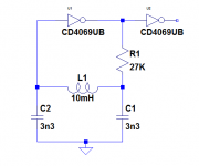
Yes, it limits the coupling between the output and the tank circuit, allowing it to oscillate more freely.Hey Elvee , the R1 of 27k you mentioned in post 23 , does it have the same function as an R in that spot for quartz oscillators ? Is it there to limit the current through the 10 mH ? How to optimize the value.
Too low, and the IC will influence the frequency, too large and oscillations will become weaker and eventually die out completely.
Use the procedure to determine the value, but I expect it to end between 10K and 40K:
The resistor can be zero to start with (or a low value like 470 ohm).
You can then increase it until the oscillations become too weak for a reliable operation.
Opt for a value 30% smaller, to ensure a good stability and reliabilty.
The inductor can be a common resistor-like type, but if you find a better one, with an adjustable core, you will be able to tune the frequency very accurately
No, the duty cycle is determined by the thresholds of the MOS transistors of the logic operator, and will always remain close to 50%You also tested heavily asymetrical capacitors . Did that change the duty cycle ?
Maybe another stupid question . But I think some of us use IR-remote control to control our diy audio equipment , I certainly do.
I'm making IR remote control with HT12 D & E . I can source these easily in country.
But only the enocoder HT12 E , not A version that has a 38Khz output to drive IR led's. No problem , I just add a 38Khz oscillator and gate it with the positive data output. It works , but the RC oscillator frequency is strongly related to the supply voltage.
With 2 AAA's that is 3.2 V to 2.2 V near empty. So the RC oscillator is just not posible.
Only way I see is like in most RC's : 455Khz resonator + divided by 12 , which is a bother an too many more components (counters/gates).
OR a 38Khz QXtal , like Mouser has (38.4 Khz ) paired with a AHC1G or even an AUP1G nand or nor gate.
First version in pic , works with RC oscillator , it gets switched on and off with EVERY bit of the 3khz data output data , just not doable with a QXtal.
Second version in pic , the oscillator starts when pressing a button on the remote and only as long as the button is pressed . The AND gate modulates the 3Khz data output with the 38,4 Khz from the QXtal.
Here's my question :
Is a quartz crystal ok for this often on/off switching ? Will it shorten it's life ?
A RC oscillator has of course no problem with it , but a QXtal is different.
And : A RC oscillator like here with SchmittTrigger gate , starts immediately , first period is slightly longer . How quickly does a quartz ocsillator start ? Is there a a short time that the frequency isn't right yet ? In that case I need to start the transmission a little later from when the button is pushed.
I have no oscilloscope , so I can't check for myself.
Thanks !
A completely different approach could use an Arduino nano. This lends itself best to a small number of switches.
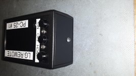
I built a special remote for LG TVs that transmits the 'power on', 'power off' or HDMI 1 codes. There are 4 TVs
side by side and the normal power toggle function doesn't work reliably. This remote continuously transmits a
code with no "repeat" codes. Repeat codes are only useful if the unit received the first code. Press and hold the
power on and just sweep it around the room until all 4 TVs are on. The .TXT file is the Arduino sketch (simply
renamed to .TXT) which could not be much simpler. Same for the hardware simplicity.
The power to the Arduino is the 'OR' of the 3 switches, any of which powers up the Arduino. The other pole of
the switch selects function. The 'activity' light is software driven and can only light if the program is running.
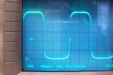
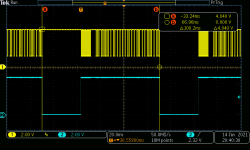
The scope photo is the modulated 38 KHz carrier in yellow and the scope trigger in blue. It transmits 10
messages per second.
G²
Attachments
No, the duty cycle is determined by the thresholds of the MOS transistors of the logic operator, and will always remain close to 50%
You'd think that the smaller cap is filled quicker and influence the duty cycle.
So to choose R1 , I need an oscilloscope . I'll try the recommended 27 k first.
Thanks Elvee.
A completely different approach could use an Arduino nano. G²
Thanks , but microcontrolers are not for me .
For only 3 switches the HT12 could be used alone too. Well the A version with build in 38kHz output.
Not necessarily: you can use a detector probe:So to choose R1 , I need an oscilloscope . I'll try the recommended 27 k first.
Thanks Elvee.
Oscillation Sniffer
It is less convenient than an oscilloscope and will only tell you the amplitude, but nothing about the frequency or shape, but in your case, it should do the job
- Home
- General Interest
- Everything Else
- Frequent on/off switching of quartz crystal oscillator