Yes I already made that oscillation sniffer .
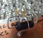
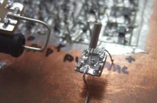
The 10mH came ... that is a big motherf : I didn't notice while ordering , I was looking at the little pic : https://www.mouser.com/ProductDetai...=sGAEpiMZZMv126LJFLh8yyVlOY2UZQmb8R6s3vr5vdo=
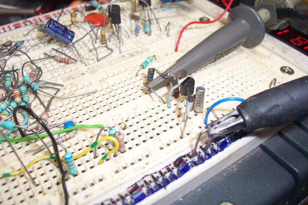
Here is the actual one ( yes like on the datasheet) , compared to the 38,4 kHz Xtals .

The 10mH came ... that is a big motherf : I didn't notice while ordering , I was looking at the little pic : https://www.mouser.com/ProductDetai...=sGAEpiMZZMv126LJFLh8yyVlOY2UZQmb8R6s3vr5vdo=
Here is the actual one ( yes like on the datasheet) , compared to the 38,4 kHz Xtals .
Attachments

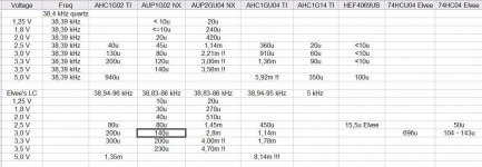
Well I've finally received all my AHC/AUP 1 gate logic to make a 38 kHz oscillator
for the IR remote . High hopes for low power AUP , for constant running quartz or
fast on/off with Elvee's LC oscillator.
The quartz osc was disappointing . I expected better , especially after good results
with frequency tests on gates and FF's in AUP , AHC (and HCS).
The AHC and AUP are on different regulators : 1,25 to 3,5 V (for AUP) and 2,5 to5,5 V (for AHC).
1,25 to 2,0 V and 3,5 to 5 V are just for information . Important is 2 x AAA range
of 3,3 to 2 V.
None get near the HEF4069UB , I rechecked them again to be ultra sure (but with
32,768 kHz Xtal).
By far the biggest disappoitments are the GU = unbuffered ! Just like Elvee's HCU
test , but these are worse ! I don't get it.
The quartz freq is the same for all devices and supply voltages .
The LC differs a little between the devices , but not more than 20 Hz from high to
low voltage. I used 1nF + 1nF + 150pF on input and 10 nF on output , 38,8 kHz
was close enough for testing. Stuck with the 10mH and 28k resistor.
While I read that Schmitt trigger inputs are not posible with quartz , I tried it
anyway with AHC1G14 , and it works for 38 kHz with the "cleanest" 50,2 % DC.
The LC and a 20 MHz Xtal did not work , but that could be the RC's around it , I
used ?
Although I'm going to try ST AUP's like 57 or 58 , maybe even a HCS04, which
may be a little better than the best so far : AHC14 , with quartz , I'm think I'm not
going to get better than the 4069UB and 60u at 3 V is not acceptable with AAA
bat's.
Elvee's LC is looking better and better despite the big 10mH . With an on/off delay
of 250us , and consumption not that important , this could be the one.
Like I said : Unbuffered are a big disappointment , even with a 20MHz xtal the numbers are awful. Luckily I didn't buy much of them.
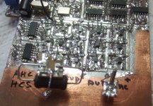
The pics are of the test PCB , with the 2 little mobile boards so that they all had the
same components , and I only had to make 2 , to test them all. (3 with the 20MHz)
All measured over 1 ohm R , so rounded numbers below 10 uA.
for the IR remote . High hopes for low power AUP , for constant running quartz or
fast on/off with Elvee's LC oscillator.
The quartz osc was disappointing . I expected better , especially after good results
with frequency tests on gates and FF's in AUP , AHC (and HCS).
The AHC and AUP are on different regulators : 1,25 to 3,5 V (for AUP) and 2,5 to5,5 V (for AHC).
1,25 to 2,0 V and 3,5 to 5 V are just for information . Important is 2 x AAA range
of 3,3 to 2 V.
None get near the HEF4069UB , I rechecked them again to be ultra sure (but with
32,768 kHz Xtal).
By far the biggest disappoitments are the GU = unbuffered ! Just like Elvee's HCU
test , but these are worse ! I don't get it.
The quartz freq is the same for all devices and supply voltages .
The LC differs a little between the devices , but not more than 20 Hz from high to
low voltage. I used 1nF + 1nF + 150pF on input and 10 nF on output , 38,8 kHz
was close enough for testing. Stuck with the 10mH and 28k resistor.
While I read that Schmitt trigger inputs are not posible with quartz , I tried it
anyway with AHC1G14 , and it works for 38 kHz with the "cleanest" 50,2 % DC.
The LC and a 20 MHz Xtal did not work , but that could be the RC's around it , I
used ?
Although I'm going to try ST AUP's like 57 or 58 , maybe even a HCS04, which
may be a little better than the best so far : AHC14 , with quartz , I'm think I'm not
going to get better than the 4069UB and 60u at 3 V is not acceptable with AAA
bat's.
Elvee's LC is looking better and better despite the big 10mH . With an on/off delay
of 250us , and consumption not that important , this could be the one.
Like I said : Unbuffered are a big disappointment , even with a 20MHz xtal the numbers are awful. Luckily I didn't buy much of them.
The pics are of the test PCB , with the 2 little mobile boards so that they all had the
same components , and I only had to make 2 , to test them all. (3 with the 20MHz)
All measured over 1 ohm R , so rounded numbers below 10 uA.
Attachments
Results look disappointing, but from your POV: these gates are logic gates, designed primarily to deal with logic signals. They also work as oscillators, but are not optimized for the task.
In fact, even the 4069 is not really optimal as an oscillator: the oscillator gates of the 4060 do much better, in terms of current consumption and difficult crystals.
Gates with hysteresis are normally not suitable for linear oscillator, at least in the regular, Colpitts configuration. You had some luck, but don't count too much on it.
I remember that Elektor had published a 32.7K oscillator circuit based on a schmitt trigger gate, but it had serious adaptations to deal with the hysteresis. It was in the late seventies/early eighties. It should be possible to dig it out.
It don't think the principle would easily be applicable to the LC version though.
The 74HC04 would have been ideal for you, as it is specified down to 2V, but you have 5 useless operators as an unwanted present....
Then again, why does that matter? Just tie their inputs to the ground or the supply.
Those fast low-voltage unbuffered inverters are just a stacked NMOS and PMOS with low threshold voltages and a huge transconductance. They are bound to draw far more overlap current than a slow inverter (-> small transconductances) meant for somewhat higher voltages (-> higher threshold voltages). In the buffered versions, you have a small, somewhat larger and large inverter in a chain and the only one that draws overlap current a large part of the time is the small input inverter, because that's the only one that's not driven by rail-to-rail square waves.
Those fast low-voltage unbuffered inverters are just a stacked NMOS and PMOS with low threshold voltages and a huge transconductance. They are bound to draw far more overlap current than a slow inverter (-> small transconductances) meant for somewhat higher voltages (-> higher threshold voltages). In the buffered versions, you have a small, somewhat larger and large inverter in a chain and the only one that draws overlap current a large part of the time is the small input inverter, because that's the only one that's not driven by rail-to-rail square waves.
I have all the Elektors ( well , the bad english ones ) , and reviewed them in august , but did not see a ST quartz oscillator.
Since the LC oscillator is an on/off one it is not important with a ST gate , but trying it anyway costed no effort.
My hope was on the AUP's because they are designed for low current near the switching point , so they should be much better than the rest. ST's have even lower current between their thesholds than the regular.
When regular gates function with quartz or even an LC , with better consumption , when why use these unbuffered ones ? Jitter at the switching point ?
Elvee's LC seems the best but the big inductor bothers me a bit. And there is Mark Johnsons idea of the turbo version with a 1 V drop , so the voltage would be between 2,2 and 1 V ( AAA's near empty or asymerical discharge) , the AUP1G02 would draw maximum 20 uA . I need to change the 1 ohm measure R to 10 ohm to get a more accurate number . DVM only shows 0,01mV.
More testing , but I like doing it.
The problem with a Schmitt-trigger crystal oscillator would be start up.
Crystal oscillators usually start with noise or with some small ringing caused by the power-up transient. The oscillation gets undamped by the amplifying part and keeps growing and growing until some non-linear effect, such as amplifier clipping, stabilizes the amplitude.
With a Schmitt trigger, when the signals are smaller than the hysteresis, it doesn't provide any gain. It therefore can't start from noise. You would need to get the crystal to oscillate at a high enough level to overcome the hysteresis before the Schmitt trigger can take over. It's the electronic equivalent of a pendulum clock that needs a push to start swinging.
It was not a standalone project; IIRC it was part of a real-time-clock, or something similar.I have all the Elektors ( well , the bad english ones ) , and reviewed them in august , but did not see a ST quartz oscillator.
Probably the early eighties.
There are much smaller 10mH inductors, but they would probably result in a less stable oscillator: the open, resistor-like ones would have a higher series resistance, meaning a lower Q, and those covered with a ferrite sleeve would be more dependent on the ferrite properties.
If you find one, you can test it anyway, and it doesn't need to be 10mH: you can scale the capacitors value to arrive at the correct frequency
The problem with a Schmitt-trigger crystal oscillator would be start up.
Crystal oscillators usually start with noise or with some small ringing caused by the power-up transient. The oscillation gets undamped by the amplifying part and keeps growing and growing until some non-linear effect, such as amplifier clipping, stabilizes the amplitude.
With a Schmitt trigger, when the signals are smaller than the hysteresis, it doesn't provide any gain. It therefore can't start from noise. You would need to get the crystal to oscillate at a high enough level to overcome the hysteresis before the Schmitt trigger can take over. It's the electronic equivalent of a pendulum clock that needs a push to start swinging.
That is right on the money Marcel .
I just tested AUP1G57 with ST inputs and I had to vary the supply voltage to make it (the quartz) start. Sad because it draws little current.
With one of the inverters of HCS14 it started but at 3,3 V it stalled .
The 20 MHz oscillator and Elvee's LC won't go with either and AHC1G14 although the LC worked on the HCS14 above 3,3 V.
There are much smaller 10mH inductors, but they would probably result in a less stable oscillator: the open, resistor-like ones would have a higher series resistance, meaning a lower Q, and those covered with a ferrite sleeve would be more dependent on the ferrite properties.
If you find one, you can test it anyway, and it doesn't need to be 10mH: you can scale the capacitors value to arrive at the correct frequency
Well I can't order again from abroad , just received the mouser and TI goodies which should last me a year or so.
My local webshop has limited offerings in that range and in small size.
And with all the 'goodies' , I'm overwhelmed in work , to go find something in the boring Elektors that probably won't help me much.
Some more of today. I should have done them all over 10 ohm , or at least the ones for the 38kHz oscillator , but measuring current and levels at the thresholds , I wanted only a small drop in supply voltage and for the higher current draw at high frequencies.
AHC1G00 and 02 and AUP1G00 and 02 are not copy and past , these are very close , rounding errors 1 or 10 ohm and slightly different supply voltage variantions.
AUP's at 1,25 V , yes =<1uA , verified with a AUP1G80 D-FF to be sure it was still oscillating. 13 uA at 2V ( 3V - 2 diodes , for the turbo ) is doable BUT if its output goes to a gate on the full voltage , this one will draw some current too because its input will be nearer to the switching point.
Attachments

A fine collection of work you've put into this already, and a nice table.
Now that you have some good options for low-power oscillators, are you sure you want to stay with AAA batteries? The reason I ask is from the bad memories I have of every AAA-battery remote I owned from the 1990's. Took a while to sort, but finally realized the AAA's can't supply the peak current. None off the remotes we owned that used AA's had the problem.
The newer stuff using AAA's works OK -- but I'm pretty sure the designs are using some switching-regulator tricks.
Cheers
Last edited:
A peak current of 1A or so is sent into the IR LED, and if the batteries internal resistance is too large, it can be problematic.
All that is needed is large, low esr bypass cap across the supply. They are available in small sizes nowadays, especially in 4V.
If the shape factor is a problem, simply parallel a number of smaller ones, this will reduce the esr even further
All that is needed is large, low esr bypass cap across the supply. They are available in small sizes nowadays, especially in 4V.
If the shape factor is a problem, simply parallel a number of smaller ones, this will reduce the esr even further
That is the first I hear of problems with AAA's . I never had problems .
Oxidized contacts could be a problem , especially with leaky batteries.
Maybe IR LED's have become better , like the high efficient regular LED's , so big
1A peak currents are not needed . And like Elvee says , a good bypass cap can help.
Unless you want to zap over long distances (or in sunlight) , 100mA or so can be enough.
I'm not sure what to choose : 1 IR LED with high current or 2 with lower current .
2 AAA's are just not enough for 2 in series when going below 2,4-2,5 V.
Today I tested the limits of the good old 4069UB . I made some changes like better
measuring over a 10 ohm R and a lower supply voltage for a better re-test.
The HEF4069UB starts with 32,768 kHz Qxtal at 2,5 V and stops al the way down
to 1,6 V ! At 2,5 V it draws 1uA ! at 2 V below 1 uA , the DMM display stays at 0.
This is with 2 of its buddies as buffer and connected to the input of an LVC1G17. Amazing !
A 10 Mhz quartz starts at 3,0 V and stops at 2,55 V. At 3 V : 505uA and 2,6 V : 380uA , also buffered and connected to an LVC1G17.
2 LEDs in series are better than one, but then you have the dilemma of low-voltage operation.
You cannot have your cake and eat it; with electronics, this is not completely true though: you could implement a fall-back circuit shorting one of the LEDs under LoBatt conditions, but that sounds like a huge over-complication for a relatively mundane problem.
Consumer opto's have greatly improved: with my new TV, I can fire the remote from anywhere in the room, pointing at anywhere, including a far-away wall. It always works, almost like a RF remote.
To prevent it from operating, I need to cover the LED completely with my hand.
My previous TV was much pickier, yet it was a Panasonic
Yes shorting one of the LED's is easy , but doing it with no extra current while on stand by , too much of a bother for the little gain.
IR reflects from the walls so you don't have to point it to the sensor.
I prefer IR remotes , not causing harm like RF's , or all the variations of bluetooth and others from smartphones.
IR reflects from the walls so you don't have to point it to the sensor.
I prefer IR remotes , not causing harm like RF's , or all the variations of bluetooth and others from smartphones.
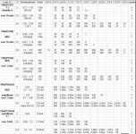
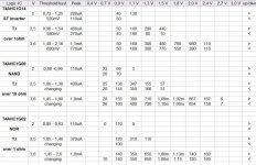
If you wanted to confirm why the unbuffered consume so much more current , just compare the current draw with rising of falling voltages on their input.
While the 'normal' ones top out at around 700 uA (AUP at 3,6 V) , or 1,8mA ( AHC at 3,6 V) , the 2 unbuffered go to around 8 or even 12 mA . They do have nice slopes, not like the regular that have a weird changing ( or oscillating ) part near their switching point or rather switching area. (Added the 2 Schmitt triggers to compare , clean switching at an even lower current draw)
While the 'normal' ones top out at around 700 uA (AUP at 3,6 V) , or 1,8mA ( AHC at 3,6 V) , the 2 unbuffered go to around 8 or even 12 mA . They do have nice slopes, not like the regular that have a weird changing ( or oscillating ) part near their switching point or rather switching area. (Added the 2 Schmitt triggers to compare , clean switching at an even lower current draw)
Attachments
This makes me think: why are we sweating with logic gates when there are other options?
One that was hiding in plain sight, is perfectly obvious yet escaped us both, is the good'ol discrete oscillator:
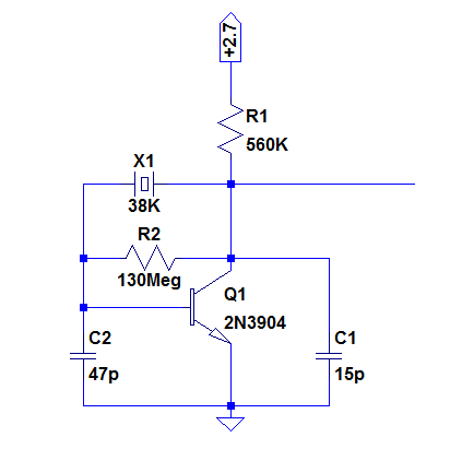
It took a minute or two to test it:
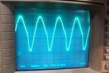
And here is the result:

Current consumption: <3µA!
You can leave it on permanently without any problem
One that was hiding in plain sight, is perfectly obvious yet escaped us both, is the good'ol discrete oscillator:
It took a minute or two to test it:
And here is the result:
Current consumption: <3µA!
You can leave it on permanently without any problem
Attachments
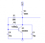

One that was hiding in plain sight, is perfectly obvious yet escaped us both, is the good'ol discrete oscillator
However, if 60 uA consumption is unacceptably high, I recommend you design a free running, always-on, discrete component crystal oscillator that consumes, say, 3 uA, plus an output enable gate that swings rail to rail for whatever the supply voltage happens to be at the moment (while the battery discharges). The enable gate will probably consume another 3 uA. Remember: if the wristwatch guys can make a low current crystal oscillator that's always on, so can you!
Not really sweating Elvee . The tests I've done are a part of a bigger comparison test of 74HCS, AHC , AUP and good old HC. Of course without the need for a good 38kHz oscillator I wouldn't have bought the unbuffered ones .
Sure discrete could be an option . I was never into those because I don't understand how they work. While going over the Elektors , I ve seen a few discrete ones , but didn't copy them .
I'm surprized you have a 38 kHz quartz ... 😱
Not an everyday item. I was (am ?) 90 % sure I would use your LC oscillator.
Looking at your design : R2 130Mohm ? Transistor can be a BC84x one ?
Oscilloscope pic is with a 1:10 probe , I hope ? A ST gate will clean that up , not that I expect much better from a 4069UB output.
Worth a try ! Thanks .
- Home
- General Interest
- Everything Else
- Frequent on/off switching of quartz crystal oscillator