Member
Joined 2018
A HAPPY NEW YEAR GUYS,
I started a new FreeDSP project named "FreeDSP Catamaran A/B"
"Catamaran" comes from Stacked Dual-mono construction boards. It intends to use a 96kHz sampling 4-way stereo crossover dividing network application.
"A/B" means dual boot EEPROM feature as same as my previous FreeDSP products.
That construction improves cross-talk performance and increases the number of programming steps.
A highlight of this board design is a high-performance differential mode ADAU1701 embedded ADC circuit.
It reduces remain noise by 3dB and a large signal (-20dB to 0dB) distortion drastically.
According to my experiment on FreeDSP Classic SMD A/B overall(ADC --> DAC) THD performance indicates as follows...
Frequency | Single-End | Differential
100Hz | 0.00723% --> 0.00287%
1kHz | 0.00642% --> 0.00171%
It will satisfy most cases of audio users' channel divider applications.
CyberPit
Last edited:
Member
Joined 2018
Hello again
Here are the Planned Features of FreeDSP Catamaran A/B.
CyberPit
Here are the Planned Features of FreeDSP Catamaran A/B.
- 1in4out RCA jacks on each PCB
- High-Performance differential monaural ADAU1701 ADC circuit
- A/B Selectable Dual boot EEPROMs
- Common-mode Choke filtered Power Supply Input
- 0805(2.0mm x 1.25mm) SMD Resistors & Capacitors
- Through-Hole Ele-Caps on the Audio Path
- Unity Gain Analog Audio Input and Output (2V RMS)
- Absolute Phase transparent. (No need to invert Output Phase)
- Power-ON/OFF/Reboot Anti-Pop Audio Mute
- Buffered TDM Interlink I/O Header (with Enable control)
- Rotary Pots x4 for AUXADC
- Mains Power Switch
- A/B Program Select switch
- Reset(Reboot) Push Switch
- MP0/MP7/MP9 controlled LED Indicators
- LED Power Indicator
CyberPit
Member
Joined 2018
Member
Joined 2018
The FreeDSP Catamatan A/B board design is on the way...
Attachments
-
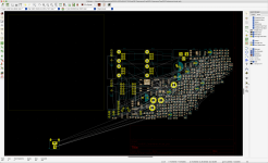 1 FootprintAssigned.png415.1 KB · Views: 235
 -
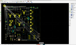 2 AutomaticPlaced.png509.6 KB · Views: 223
 -
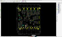 3 Physically Placed.png329.8 KB · Views: 225
 -
 4 Ratsnest.png368.2 KB · Views: 234
 -
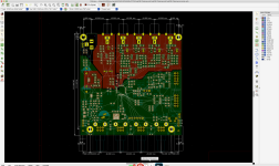 5 Zone Placed.png419.7 KB · Views: 238
 -
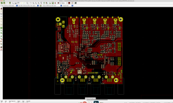 6 Manual PreRoutefFill.png330.9 KB · Views: 275
 -
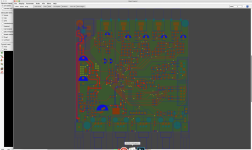 7 FreeRouting.png440.4 KB · Views: 247
Hello Pit.Hello again
Here are the Planned Features of FreeDSP Catamaran A/B.
Now I'm drawing a schematic... 🤔
- 1in4out RCA jacks on each PCB
- High-Performance differential monaural ADAU1701 ADC circuit
- A/B Selectable Dual boot EEPROMs
- Common-mode Choke filtered Power Supply Input
- 0805(2.0mm x 1.25mm) SMD Resistors & Capacitors
- Through-Hole Ele-Caps on the Audio Path
- Unity Gain Analog Audio Input and Output (2V RMS)
- Absolute Phase transparent. (No need to invert Output Phase)
- Power-ON/OFF/Reboot Anti-Pop Audio Mute
- Buffered TDM Interlink I/O Header (with Enable control)
- Rotary Pots x4 for AUXADC
- Mains Power Switch
- A/B Program Select switch
- Reset(Reboot) Push Switch
- MP0/MP7/MP9 controlled LED Indicators
- LED Power Indicator
CyberPit
I'm a bit late but i've few questions about.
The project indeed is really interesting.
Why not balanced outputs as well?
Any possibility to link two boards in order to have something like 8 channels stereo?
Ciao and greetings from Italy.
Maurizio
Member
Joined 2018
Hi Guys,
The TDM-interlink will be able to pass 8 channel data between 2 boards. So you can use 3way Stereo + Mono-Subwoofer with a pair of FreeDSP Catamaran A/B boards or using four FreeDSP Catamaran A/B boards for 2in 8out x 2times separate system. Of course, you can produce a balanced output 4way stereo system as well with these boards 4times.😎
CyberPit
Well, I have a plan to order this board to JLPCB PCBA service. They can accept MOQ=2 boards. So, the group buy is not necessary considering with international shipping costs. But maybe I'll share a 10 boards order with my local friend(s).Are you thinkg Group buy down the line?
🙄 Maurizio, thanks for giving me an idea. I'll add 3pin output headers for XLR 32C receptacles. Using two outputs with inverting options makes the possibility to use 2way balanced output crossover.The project indeed is really interesting.
Why not balanced outputs as well?
Any possibility to link two boards in order to have something like 8 channels stereo?
Ciao and greetings from Italy.
Maurizio
The TDM-interlink will be able to pass 8 channel data between 2 boards. So you can use 3way Stereo + Mono-Subwoofer with a pair of FreeDSP Catamaran A/B boards or using four FreeDSP Catamaran A/B boards for 2in 8out x 2times separate system. Of course, you can produce a balanced output 4way stereo system as well with these boards 4times.😎
CyberPit
Member
Joined 2018
Hi Maurizio-San,
On the other hand, adding just headers for XLR is ...
That's why I do not add a balanced driver for each output of FreeDSP Catamaran A/B.
CyberPit
Technically yes, Using the same type of circuit which I used in ADC part. (Just 2 more resistors need for each output) But I think it does not make sense for the following reasons...So is not possible to have 4 balanced output from the same pcb?
- Not enough PCB space for onboard XLR connectors.
- Unbalanced RCA-pin input and output will be enough for folks.
- Increasing signal path length makes no specific/audible advantages.
On the other hand, adding just headers for XLR is ...
- No additional circuit is required.
- Nothing to lose for RCA output only users.
- Using two outputs improves the DAC side signal-to-noise ratio by 3dB.
That's why I do not add a balanced driver for each output of FreeDSP Catamaran A/B.
CyberPit
Member
Joined 2018
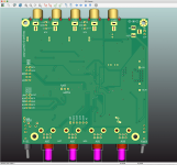
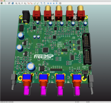
Design Completed!

MP9 indicator LED was not available because it was already used another function.
The next process is choosing SMT parts at JLPCB PCBA.
CyberPit
MP9 indicator LED was not available because it was already used another function.
The next process is choosing SMT parts at JLPCB PCBA.
CyberPit
Attachments


Last edited:
Having balanced XLR outputs via output header sounds OK (too bad no ability to get 4 balanced outputs from 1 PCB as the other user asked), but are additional components required after the output header or could the XLR connectors be directly wired to the board via the header?
Is there a master volume controller that attenuates all 8 channels simultaneously? If so, is it encoder-based or a pot?
Could you please make sure all low-voltage signal headers & connectors are using gold-plated contacts?
The shaft for the pot (?) near JP3 is interfering with the mounting hole.
The two small 3-pin white headers between the RCA jacks look like headaches waiting to happen (plugging/unplugging).
Since this is aimed toward single-ended use, will there be an onboard means (either permanent or disable-able) to lift ground loops?
What are the input capacitors? Bipolar electrolytic? Capacitance?
Will it be possible to provide estimated/simulated noise performance figures, IMD, THD at e.g. 5 kHz, multi-tone, ... ?
Sorry for all the questions and thanks very much for the community support!
Last edited:
WOW.!!!!Design Completed!
View attachment 1012937
MP9 indicator LED was not available because it was already used another function.
The next process is choosing SMT parts at JLPCB PCBA.
CyberPit
You 're a PCB designer Master.!!!
Very nice.
I share with you my dream....so let me know than what i would need to make it real.
The target is to build up a multichannel system.. 8 ways stereo.
It's mandatory for me to use balanced outputs for several reasons.
Considering this..how many pcb i wuold need to each channel and how i can connect one each other..? Through the TDM interlink?
I like to have the xlr sockets on the pcb..so from there i can wire the xlr sockets on the chassis.
Many thanks for your support.
Apologize for my english mistakes..i hope that everything was clear to you.
Maurizio
Member
Joined 2018
Thanks for giving me comments.

One of ADAU1701 embedded AUXADC will be used for this control. The coefficient for volume operation can be transferred via TDM link if you wanted.
(You can keep OUTPUT3 (also PUTPUT1) RCA jacks when you use XLR output option.
The left header between OUTPUT0 and OUTPUT1 is JST-EH type connector. This can mount both RCA and this Header.
Does anyone want to have more spaces for these caps?
A large signal distortion performance improvement of ADC was tested as I described before.
The attached block diagrams will help to understand my system concept of FreeDSP Catamaran A/B.

Regards,
CyberPit
Master Volume will be placed at the last part of DSP processing. There's no gang error because it's digital.Is there a master volume controller that attenuates all 8 channels simultaneously? If so, is it encoder-based or a pot?
One of ADAU1701 embedded AUXADC will be used for this control. The coefficient for volume operation can be transferred via TDM link if you wanted.
I'm not sure, it depends on your pocket.💴Could you please make sure all low-voltage signal headers & connectors are using gold-plated contacts?
The RESET button is not necessary, just for in-case. Just turn OFF and ON the power switch acts as the same thing. You can use a short shaft-type push switch and drill a small hole on the front panel if you want to use this. Using a push pin for a SIM card will fit this purpose.The shaft for the pot (?) near JP3 is interfering with the mounting hole.
The right header between OUTPUT3 and OUTPUT2 is JST-XH type connector. This requires removing OUTPUT2 RCA Jack.The two small 3-pin white headers between the RCA jacks look like headaches waiting to happen (plugging/unplugging).
(You can keep OUTPUT3 (also PUTPUT1) RCA jacks when you use XLR output option.
The left header between OUTPUT0 and OUTPUT1 is JST-EH type connector. This can mount both RCA and this Header.
Well, a good question. The input terminal is not a differential design, but you can modify the R92 from 0 ohms to 10-100 ohms if you want to loosen GND connection between the signal source equipment.Since this is aimed toward single-ended use, will there be an onboard means (either permanent or disable-able) to lift ground loops?
My recommendation is Audio-grade Unipola Ele-Caps or MKH Film-Caps.What are the input capacitors? Bipolar electrolytic? Capacitance?
Does anyone want to have more spaces for these caps?
Most of the design inherits from my FreeDSP Classic SMD (Plus-II) A/B. So the fundamental performance will be the same start points. Using independent multiple ADC/DAC decrease noise level 1 by the square root of 2 (i.e. -3dB) is just a rational explanation. (Not verified yet)Will it be possible to provide estimated/simulated noise performance figures, IMD, THD at e.g. 5 kHz, multi-tone, ... ?
A large signal distortion performance improvement of ADC was tested as I described before.
The attached block diagrams will help to understand my system concept of FreeDSP Catamaran A/B.
Regards,
CyberPit
Attachments
IMO balanced outputs are rather important for a device like this. They allow longer analog leads to physically remote amps located by the speakers and break ground loops likely to arise when feeding data from a PC/modern notebook with isolation class I power brick.
Member
Joined 2018
I'm wondering...
I would like to know, How many percentages person has three or more numbers of balanced input amplifiers? Belonging consumer, amateur, and DIY freaks...
If this product was intended to use by professionals, I fully agree with this request. But I'm feeling makes no sense to add XLR balanced output for each output.
This board concept is not for high-end nor professional's. A simple and easy-to-challengeable 10cm x 10cm board policy is important for DIY'ers.
Anyway, if their many request posts replyed I will develop an optional XLR balanced output driver board for fulfilling those demands.
CYberPit
Last edited:
IMO many class-D amp chips (except for Tripaths from what I remember) have balanced inputs, and many boards with these chips allow balanced connection (if not directly, then with a bit of simple DIY). I would assume a number of users would use class-D amps for multichannel as they are small, efficient, and inexpensive, easy to build into the speakers etc. But that's just my view from the outside.
Agree with phofman, Class D amps with balanced inputs are very popular and quite economical nowadays (see Topping and other Class D products reviewed over at Audio Science Review). Even disregarding the ground loop immunity, many people would still choose to use those amps due to their price/performance.
https://www.audiosciencereview.com/.../topping-pa3s-review-desktop-amplifier.27079/
https://www.audiosciencereview.com/forum/index.php?threads/topping-pa5-review-amplifier.28512/
https://www.audiosciencereview.com/forum/index.php?threads/buckeye-6-channel-amplifier-review.18579/
https://www.audiosciencereview.com/.../topping-pa3s-review-desktop-amplifier.27079/
https://www.audiosciencereview.com/forum/index.php?threads/topping-pa5-review-amplifier.28512/
https://www.audiosciencereview.com/forum/index.php?threads/buckeye-6-channel-amplifier-review.18579/
Dear Pit.
My two cents about the xlr outputs.
As Phofman and 454sull said already, having xlr outputs available is a must.
Who's approaching a DSP will use it with a Class D amplifier most of the time.
All the best Class D Modules ( ice power...Powersoft...Hypex..) have balanced inputs for several reason.
In my opinion balanced connection sound always better than unbalanced.
So why not N. 4 xlr outputs..this will rise up the level of the board and believe me many more users will love to have it available.
Who is approaching a DSP is looking for high end for sure..
Maurizio
Something more...
I know i'm closer to be killed by you 🙂
I do not see any digital input available ..why not? ADAU 1701 accept it..
For who like to enter directly with a digital signal would be perfect..one D/A conversion only.
I would prefer to have a Molex connector for the 12V supply instead the one actually used.
Ciao and thanks a lot to share your project with us.
Maurizio
Member
Joined 2018
454Casull-San, and Maurizio-San,
Thanks for explaining your situation.
The start point of this project is "Get a High-performance (Not high-end) from incredible cheap SoC peripherals"
In other words, It comes from my technical interests. So I'm sticking to using a Single end(Not bi-polar) Powe supply, Solidstate muting device, and SoC embedded ADC/DAC. It a cheap but good enough for most RCA pin-connected applications. Those are my main focus on this project. XLR connection users will not use such a chap DSP embedded Codecs. (Sorry, it's my personal opinion)
BTW I'm thinking about an output driver circuit that has a feature of differential RCA output(Not Balanced) circuit. Near floating-GND feature will be the most beneficial one for unbalanced connected users. I believe that may fit for this project than XLR balanced outputs. How do you think about this idea?
Designing Pleasure
CyberPit
- Home
- Source & Line
- Digital Line Level
- FreeDSP Catamaran A/B