Hi Pit.
Processing 4 rca channel or 4 xlr channer will not change the dsp processing load too much.
Why not N. 4 connectors for balanced connections instead the rca plugs.
People who wants to convert xlr to rca can do it easily.
But...believe me ...most of the class d amps have balanced input.
Do not forget to think about a digital port..!!!
Why to convert A/D and than D/A again..
Having a digital input will decrease the dsp processing load as well i suppose.
Ciao.!!
Member
Joined 2018
Hi Maurizio-San,
I guess you are expecting the much higher class system design concepts than such cheap DSP embedded codecs. Three times PA3 costs $360. It's too expensive for the mainstream Sunday DIY hobbyists. They are enjoying buying and connecting the $10 made-in Cina TPA3116D2 Boards or something like that at eBay or Ali-express. I guess you need much more audiophile-oriented designed DSP boards such as Shark, ADAU1466 with High-Class ADC, and DAC chips. Maybe your needs will not for this 48pin SoC capable things. It will be realized by another solution. Should be taken another way...
We should be much more focused on connecting digitally than Analog today. For example. A FreeDSP ADAT-IO-x4c enables to connection 8 channel I2S signals via a single cable. My TAS6422 Amplifier board has the capability to connect I2S directly via HDMI-Cable. There are no losses even if using a long cable. Should be connected digitally between DSP and DAC (or Class-D amplifier which has digital inputs) is my current idea for higher class approach. (Not this project)
Anyway, I designed a new output circuit idea for RCA output. A differential output circuit with GND loosen (not completely lifted) enables to eliminate ground-loop hum noising. (Maybe, not tested yet).
Current MFB LPF Output Circuit

A new Idea, Differential Output Circuit

This circuit will act as Common-mode Choke for the target amplifier.
If I implement this, perhaps it take much more time, Because there's very little space around this part...😱
CyberPit
I guess you are expecting the much higher class system design concepts than such cheap DSP embedded codecs. Three times PA3 costs $360. It's too expensive for the mainstream Sunday DIY hobbyists. They are enjoying buying and connecting the $10 made-in Cina TPA3116D2 Boards or something like that at eBay or Ali-express. I guess you need much more audiophile-oriented designed DSP boards such as Shark, ADAU1466 with High-Class ADC, and DAC chips. Maybe your needs will not for this 48pin SoC capable things. It will be realized by another solution. Should be taken another way...
We should be much more focused on connecting digitally than Analog today. For example. A FreeDSP ADAT-IO-x4c enables to connection 8 channel I2S signals via a single cable. My TAS6422 Amplifier board has the capability to connect I2S directly via HDMI-Cable. There are no losses even if using a long cable. Should be connected digitally between DSP and DAC (or Class-D amplifier which has digital inputs) is my current idea for higher class approach. (Not this project)
Anyway, I designed a new output circuit idea for RCA output. A differential output circuit with GND loosen (not completely lifted) enables to eliminate ground-loop hum noising. (Maybe, not tested yet).
Current MFB LPF Output Circuit
A new Idea, Differential Output Circuit
This circuit will act as Common-mode Choke for the target amplifier.
If I implement this, perhaps it take much more time, Because there's very little space around this part...😱
CyberPit
Last edited:
Member
Joined 2018
I would like to know. I guess this is not N.4. Can you show me the link to "N.4 connector" ?Why not N. 4 connectors for balanced connections instead the rca plugs.
People who wants to convert xlr to rca can do it easily.
I don't think so. It's not a major in the product. Especially cheap DIY boards...But...believe me ...most of the class d amps have balanced input.

CyberPit
Last edited:
Good Morning Pit.
Have a look to this board.
https://it.aliexpress.com/item/1000...&terminal_id=50ad50bd56ad4a8aa040c1ef6699c821
It's plenty of DSP with unbal outputs based on the ADAU 1701..at really cheap price..
Considering you're developing something new..why don't do it different.
https://ez.analog.com/dsp/sigmadsp/f/q-a/64763/adau1701-adc-noise---even-with-new-design
Here just some ideas.
That's just my point of view of course.
Have a good day.!!
Maurizio
Attachments
Member
Joined 2018
Thanks, Maurizio
"N.4" connector is also called a "JST-HX" connector. (It's in Ki-Cad Footprint Library)
I guess you can buy EDSP-1701-24-A it will more fit-on your needs than FreeDSP Catanaran A/B and it is quite a chapter than DIY. There are no constraints to do! 😜
By the way, I need to explain some reasons why not do the same way...
The last concern thing was the unbalanced Input stage. Today I looked at JLPCB's PCBA parts stock lists and I found OPA1632 is available! So I gonna change the input circuit design to the differential type RCA input. Finally, I could establish the differential RCA pin I/O (Not Balanced) design concept that I've never seen before. I would like to say thank you to Maurizio and 454Casull. You drove me to make better designs and concrete concepts.
Best Regards,
CyberPit
"N.4" connector is also called a "JST-HX" connector. (It's in Ki-Cad Footprint Library)
I guess you can buy EDSP-1701-24-A it will more fit-on your needs than FreeDSP Catanaran A/B and it is quite a chapter than DIY. There are no constraints to do! 😜
By the way, I need to explain some reasons why not do the same way...
- My main concept is "Everything on the board". (not needed separate I/O breakout boards, etc...)
- Must have four-parameter controls (MP9 should be used for AUXADC)
- No ADAU1701 peripheral pins left. (Fully occupied by embedded features)
- Maximum 10cm x 10cm board size.
- Try to use only the available parts at JPCPB's PCBA service.
- I don't like extending the signal path length (Adding fixed driver stage is also making no sense from this point of view)
The last concern thing was the unbalanced Input stage. Today I looked at JLPCB's PCBA parts stock lists and I found OPA1632 is available! So I gonna change the input circuit design to the differential type RCA input. Finally, I could establish the differential RCA pin I/O (Not Balanced) design concept that I've never seen before. I would like to say thank you to Maurizio and 454Casull. You drove me to make better designs and concrete concepts.
Best Regards,
CyberPit
Last edited:
That board is not available anymore, that's why i asked you somethig like that.
One last..request...i hope you can make me happy 🙂
Can you route the direct signal from the adau1701 on the side of the rca connectors? As we do have it we could add an external pcb with the unbalanced to balanced converter...or a signal transformer...
Just two pads..one for the ground and one for the signal..
Do you think is feasible?
Ciao.!!
Member
Joined 2018
Hello DIY folks!
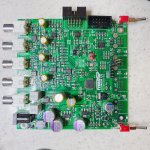
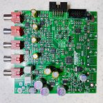
Now I complete the design of FreeDSP Catanaran A/B and its optional Balanced output Board.
Here's version 0.2 DSP Main Board

And an optional Balanced output Board.

Now assigning PCBA parts for JLPCB...
CyberPit
Now I complete the design of FreeDSP Catanaran A/B and its optional Balanced output Board.
Here's version 0.2 DSP Main Board
And an optional Balanced output Board.
Now assigning PCBA parts for JLPCB...
CyberPit
Attachments
-
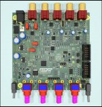 FreeDSP_Catamaran0v2TopView.jpg527.3 KB · Views: 125
 -
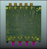 FreeDSP_Catamaran0v2BottomView.jpg370.5 KB · Views: 121
 -
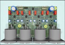 BalancedDriverBoard_RayTrace.jpg334.6 KB · Views: 110
 -
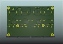 BalancedDriverBoard_BottomRayTrace.jpg191.2 KB · Views: 125
 -
FreeDSP_CatamaranSchrmatic0v2.pdf273 KB · Views: 163
-
BalancedDriverBoardSchematic0v1.pdf108.6 KB · Views: 162
Member
Joined 2018
Thanks, Piersma-San
I just estimated Board and SMT costs at JLPCB.
It costs 83.2USD for 2 SMT boards of 5 bare boards.
USD133.79 costs for 10 SMT boards.
Shipping costs and shortage of stock parts (EEPROM and Muting-BJT) are not included.
You need to order other these and all through-hole parts and mount it by your DIY spirit😉
Special thanks to Maurizio, you inspire me with seviral ideas.
CyberPit
Attachments

Hi Pit.Thanks, Piersma-San
I just estimated Board and SMT costs at JLPCB.
It costs 83.2USD for 2 SMT boards of 5 bare boards.
USD133.79 costs for 10 SMT boards.
Shipping costs and shortage of stock parts (EEPROM and Muting-BJT) are not included.
You need to order other these and all through-hole parts and mount it by your DIY spirit😉
Special thanks to Maurizio, you inspire me with seviral ideas.
CyberPit
Great work.!!
Looking to place the first order @ JLC PCB.
Many Thanks.!!!
Member
Joined 2018
I found a mistake in the Optional Balanced Driver Board BOM.
From U1 through U4 should be OPA1632. PCB design is no need to change.
The attached files are for corrections. (Git-hub is updated already)
CyberPit
From U1 through U4 should be OPA1632. PCB design is no need to change.
The attached files are for corrections. (Git-hub is updated already)
CyberPit
Attachments
Member
Joined 2018
Now I'm in the evaluation step of FreeDSP Catamaran A/B.
There are some parts that need to change, so please wait for a while if you make...
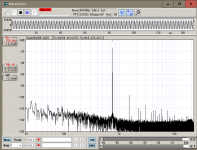
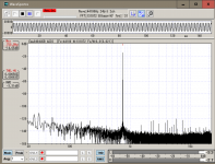
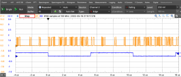
The attached spectrum graphs are overall audio performance (ADC->DSP-DAC)
The left one is Single-Ended mode, and the last one is Differential ADC mode.
Extremely low distortion and cheap embedded DSP codec had realized... 😎
CyberPit
There are some parts that need to change, so please wait for a while if you make...
The attached spectrum graphs are overall audio performance (ADC->DSP-DAC)
The left one is Single-Ended mode, and the last one is Differential ADC mode.
Extremely low distortion and cheap embedded DSP codec had realized... 😎
CyberPit
Attachments

Member
Joined 2018
Now I have completed version 0.21 board hardware evaluation.
Issue fixed release version 1.0 design files and JLPCB PCBA order format files are committed to the FreeDSP Git-Hub page.
4way Stereo Crossover Divider and 2.1chnnel 3way Crossover SigmaStudio project files will be ready soon...
CyberPit
Issue fixed release version 1.0 design files and JLPCB PCBA order format files are committed to the FreeDSP Git-Hub page.
4way Stereo Crossover Divider and 2.1chnnel 3way Crossover SigmaStudio project files will be ready soon...
CyberPit
Attachments
Hi Pit good morning. Any USBi interface is ok to connect with Sigma studio? Is Sigma Studio detecting boards connected through the TDM interlink?
Many thanks in advance.
Maurizio
Many thanks in advance.
Maurizio
Member
Joined 2018
HI Maurizio,
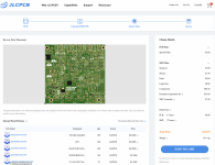
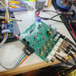
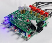
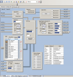
The attached image is my current evaluation setting. (fs=96kHz, TDM8 Interlinked, 4 Audio + 4pot information))
An Independent USBi connector is provided on each board. So you can write Master or Slave configuration firmware separately.
A/B program selection is linked via the strikethrough pin header.
CyberPit
No, TDM Interlink has 8 data slots. But it can be used only for Audio Data and AUX-ADC potentiometer positions etc... (Not for configuration)Is Sigma Studio detecting boards connected through the TDM interlink?
The attached image is my current evaluation setting. (fs=96kHz, TDM8 Interlinked, 4 Audio + 4pot information))
An Independent USBi connector is provided on each board. So you can write Master or Slave configuration firmware separately.
A/B program selection is linked via the strikethrough pin header.
CyberPit
Attachments
Hi Pit.
So..basically i can transfer the analog in of one board to the second using the tDM interlink right?
But..any board must be programmed separately...do i get it right?
Maurizio
So..basically i can transfer the analog in of one board to the second using the tDM interlink right?
But..any board must be programmed separately...do i get it right?
Maurizio
Member
Joined 2018
Hi Maurizio,
on both boards.
CyberPit
Yes, you can transfer up to 8ch Audio streams to another board.can transfer the analog in of one board to the second using the tDM interlink right?
If you want to have a Master Volume or stereo tracked controls. You need to program the un-asymmetrical designed firmware codes. If you do not use TDM-LINK, you can download the same codesBut..any board must be programmed separately...do i get it right?
on both boards.
CyberPit
- Home
- Source & Line
- Digital Line Level
- FreeDSP Catamaran A/B