@tomik,
is your SSD1309 display working correctly?
I use this one but it stays dark (1,54 Zoll (XXL) OLED - Arduino Raspberry Pi SPI Interface 128x64 Display SSD 1309 1306 - MAKERSHOP.DE).
is your SSD1309 display working correctly?
I use this one but it stays dark (1,54 Zoll (XXL) OLED - Arduino Raspberry Pi SPI Interface 128x64 Display SSD 1309 1306 - MAKERSHOP.DE).
Yes, I have this one: 2.42" inch 12864 OLED Display Module IIC I2C SPI Serial for Arduino – diymore
I had some trouble with the reset signal at first. Simply pulling it high did not seem to work, it needed RC delay. Also the address select pin had to be pulled high to set the i2c address correct. There’s this youtube video on the spi to i2c conversion which had in the comment section a note about the RC delay for the reset: Converting an SPI OLED to i2c 2.42in. DIYmore SSD1309 - YouTube
I had some trouble with the reset signal at first. Simply pulling it high did not seem to work, it needed RC delay. Also the address select pin had to be pulled high to set the i2c address correct. There’s this youtube video on the spi to i2c conversion which had in the comment section a note about the RC delay for the reset: Converting an SPI OLED to i2c 2.42in. DIYmore SSD1309 - YouTube
Anyone tried to change sample rate? What I have gathered:
- in SigmaStudio you use the "Set System Sampling Rate" control on the top tool bar
- then in the Hardware Configuration you change the START PULSE to Base_Fs x 2 (to get 96kHz)
- plugin.cpp there is sampleRate variable, which is used for filter coefficient calculation
Anything else, for example DAC config? How about the Serial output config in Hardware Configuration?
Reason I'm asking I noticed some high frequency roll-off on some of the filters when comparing to minidsp which is running at 96kHz as opposed to 48kHz for the aurora dsp. Not really sure yet does it matter when measuring acoustic response of the speaker (I'm not there yet), but at least on the line level measurements it is visible. And you can see the effect on SigmaStudio simulation as well when comparing 48kHz/96kHz sample rates, so it is not HW related.
On the positive side even without enclosure the measured THD/THD+N performance of the freedsp aurora exceeds minidsp 4x10HD on my measurements by quite a good margin. Let's see does it have effect on the noise levels when I get everything inside enclosure. That is next thing for me.
Thanks.
Hi,
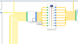
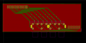
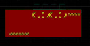
i tried to make a small 8 channel rca board
it's essentially the addon board b with only the rca section
i'm planning to use it on the input and output sections application is a car audio dsp
it was a my first time using kicad let me know if this idea works before i make it 😀
ive attached the .kicad and .pro file in a .7z if anyone wants to check it out!
Attachments
@tomik For changing the sample rate you have to do the following steps:
1) Change your sigma studio file for the new sample rate
2) Recompile your plugin with sigma2aurora.py
3) Change the value sampleRate in plugin.cpp
4) Reconfigure the DAC for the new sample rate in AK4458.cpp
5) Recompile the ESP32 firmware with ArduinoIDE and upload it.
I know it would be better that you can change the sample rate inside the GUI, this will be a good feature for a coming release.
@NoOnes2 I did not look at your file but basically you have to copy the RCA input section from AddOn-B including the 220K termination. Replace the DIP switches by a wire. For ouput let the cold output floating. Don't connect it to ground because it will make the the output section clipping then.
Raphael
I am using the Aurora dsp and am ready to move start creating my own sigma studio design and customize the platform.Hello,
I would like to introduce my newest design of the freeDSP family: freeDSP-aurora. It was already introduced in the freeDSP main thread, but there the idea came up to open a new thread only for freeDSP-aurora.
freeDSP-aurora is a one board DSP solution. It all started with the development of a DSP powered subwoofer amplifier. Once the prototype of this amplifier was presented on the German forum diy-hifi.forum.de a fruitful
- Supporting sample rates between 44.1kHz and 192kHz
To make using as easy as possible I wrote my own app that controls the DSP via Bluetooth. The app runs on
I am sure you will have a lot of questions because the board has so many features. Please feel free, to ask me!
Raphael
what I cannot figure out is how to set the akm adc and dac to 96k sampling rate.
anyone know
Hi! did you try what was said in the post above your question? 🙂I am using the Aurora dsp and am ready to move start creating my own sigma studio design and customize the platform.
what I cannot figure out is how to set the akm adc and dac to 96k sampling rate.
anyone know
another question; can I use the (balanced life) XLR output board to drive amps with unbalanced (RCA) input and balanced (XLR) input amps at the same time?
When soldering a cable (XLR to RCA), I need to connect the RCA-pin to positive and RCA-sleeve to GND and leave the negative floating, right?
need to double check as I’m really scared of making a mistake after finally scoring a board 😀
I have not tried it yet, but reading but it does make sense when I read it.Hi! did you try what was said in the post above your question? 🙂
another question; can I use the (balanced life) XLR output board to drive amps with unbalanced (RCA) input and balanced (XLR) input amps at the same time?
When soldering a cable (XLR to RCA), I need to connect the RCA-pin to positive and RCA-sleeve to GND and leave the negative floating, right?
need to double check as I’m really scared of making a mistake after finally scoring a board 😀
for your question...I often drive more than 2 amps with the same output, since the input impedance is high you can get away with that, but mixing balanced and unbalanced means that that both will be unbalanced , unless you do what you suggest and don't short ground to the signal- on the unbalanced side. If you leave signal- floating on the RCA then you will be fine but down 6db of output at that input. This is because half the signal from the XLR is not being used. This might actually be good since most RCA inputs cannot handle the same input voltage as the XLR inputs.
Read this Rane Technical Note from 1985...it is still the bible on best practices. https://www.ranecommercial.com/kb_article.php?article=2107
As I have understood:I am using the Aurora dsp and am ready to move start creating my own sigma studio design and customize the platform.
what I cannot figure out is how to set the akm adc and dac to 96k sampling rate.
anyone know
- in AK4458.cpp change the DFS[2:0] from 000b to 001b for double speed mode
- in AK5558.cpp change the CKS[3:0] from 0110b to 0011b for double speed 256fs
But I haven't tried it yet and not sure are there other settings as well that needs to be changed.
this is where I get a bit lost, I can see the AKM data sheet shows normal and double speed on the Manual Setting MCLK. Is this what you are referring to?@tomik For changing the sample rate you have to do the following steps:
4) Reconfigure the DAC for the new sample rate in AK4458.cpp
AK4458_REGWRITE( AK4458_CONTROL1, 0b00001100 );
/* Control 2 (Address: 0x01)
* bit[0] : SMUTE Soft Mute Enable : 0 Normal Operation
* bit[2:1] : DEM11-0 DAC1 De-emphasis Response : 01 Off
* bit[4:3] : DFS1-0 Sampling Speed Control : 00 Normal Speed
Changing to this line?
* bit[4:3] : DFS1-0 Sampling Speed Control : 01 DoubleSpeed
Is this the only place I need to modify? the DAC?
Will the ADC automatically clock to this new 96k Sample rage?
Good morning and Merry Xmas Raphael.@tomik For changing the sample rate you have to do the following steps:
1) Change your sigma studio file for the new sample rate
2) Recompile your plugin with sigma2aurora.py
3) Change the value sampleRate in plugin.cpp
4) Reconfigure the DAC for the new sample rate in AK4458.cpp
5) Recompile the ESP32 firmware with ArduinoIDE and upload it.
I know it would be better that you can change the sample rate inside the GUI, this will be a good feature for a coming release.
@NoOnes2 I did not look at your file but basically you have to copy the RCA input section from AddOn-B including the 220K termination. Replace the DIP switches by a wire. For ouput let the cold output floating. Don't connect it to ground because it will make the the output section clipping then.
Raphael
Any new about the new aurora dsp version? Any timeline about availability?
Many thanks in advance.
Maurizio
@tpacker: you also have to reconfigure the ADC see tomiks post. And finally: This is a diy forum. Just try it. 😉
@Maurizio: I can not say anything about timeline. It is not the ADC or the DAC only. Currently all semiconductors are hard to source and once you have found one component another one is out of stock. And I am not going to by components for 3000€ now and stock them for 7 months until the next quarter of the BOM will be available...
Sorry that is currently the situation. Thanks to the global semiconductor crisis.
Hello Raphael.
I full understand the situation.
Do you think would be possible to have the pcbs with the big FPGA chipset installed on it and then everybody else is free to find out the missing components to complete the assembly.?
At the moment a product like your is completely missing from the market. There are a lot of DSP processor , but it's always a finished product...and not something to be integrated with other components.
I hope that your DSP will be available very soon. I will be one of the first customers.!!
Have a great day.!!
Maurizio
There is no FPGA chipset on Aurora. I guess you mean the XMOS, ESP32 and the ADAU1452. Go to octoparts, type in these ICs and become frustrated.

Sorry if this has been asked before, is there any problem with the 0 VDC line (with the VDC power input) is floating and not connected to any ground?
Also, is there a problem if the USB ground and USB cable shield (drain) are connected together at the USB input header? Or should I separate the drain wire from USB ground wire so that drain and ground are "properly" isolated all the way back to the USB source?
Also, is there a problem if the USB ground and USB cable shield (drain) are connected together at the USB input header? Or should I separate the drain wire from USB ground wire so that drain and ground are "properly" isolated all the way back to the USB source?
USB Shield should only be connected to GND at one end.Sorry if this has been asked before, is there any problem with the 0 VDC line (with the VDC power input) is floating and not connected to any ground?
Also, is there a problem if the USB ground and USB cable shield (drain) are connected together at the USB input header? Or should I separate the drain wire from USB ground wire so that drain and ground are "properly" isolated all the way back to the USB source?
- Home
- Source & Line
- Digital Line Level
- freeDSP-aurora - DSP with 8 I/Os, USB Audio, S/P-DIF, ADAT, Bluetooth and Wifi contro