Ok, got it working on 192/24, just needed to change program length in DSP core from 1024 to 4x256. Sweet!
There is slight pop when MCLK is switching frequency, trying to get rid of that next.
There is slight pop when MCLK is switching frequency, trying to get rid of that next.
Nice
Really nice board ZDR. Can you elaborate on all specific functions and options of the board you designed?
Really nice board ZDR. Can you elaborate on all specific functions and options of the board you designed?
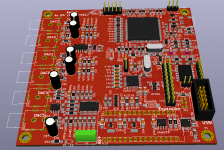
It's pretty much FreeDSP Classic but in smd + Audio Widget USB to I2S board in one. It runs in UAC1 or UAC2 mode and plays up to 24bit/192KHz (UAC2). Same expansion connector as FreeDSP Classic, you can refer to FreeDSP doc for pinout and specs. There is still ADC0 and ADC1 input on board, so you can either use that or I2S output from Audio Widget (default).
There is one additional voltage regulator (ADP151) before analog circuitry if you compare it to FreeDSP classic, to isolate further analog half of the board from digital noise.
There is one additional voltage regulator (ADP151) before analog circuitry if you compare it to FreeDSP classic, to isolate further analog half of the board from digital noise.
Same opamp used as on the classic Free DSP version? Maximum outputvoltage?
Yep, everything is the same apart from added voltage regulator for op amp.
I'm sorry if this has already been asked in the thread.
How would one go about wiring a pot(lin/log?) to the GPIO-header to get volume control in the LF of a two-way crossover? Both physically and "virtual" (SigmaStudio).
I did have my FreeDSP classic(let's call it board1 as I have two fully populated) working in the main system apart from Left HF. The left HF issue is not related to the DSP, but is the old PIO's having died on my in the physical crossover between the Dayton Reference 7" alu mid and B&G Neo 8 HF.
I have new caps for both channels on the way from Hifi-collective. I went with the JB JFX series of MKP caps, simply because they're affordable and supposedly good.
With any luck I'll get them this week, if so I can re-cap the crossovers and get on with integrating the FreeDSP Classic in to the main system.
Until I get a good DAC working as a slave to the ADAU1701, I'm thinking I'll use a DIY Y-cable to split the signal from the preamp, sending the mids/highs straight to the amp and the LF to FreeDSP and then on to amp.
Letting the FreeDSP handle LF crossover and dipole compensation only to begin with.
But since I don't have a windows PC close enough to the stereo, I'd need to disconnect stuff before adjusting the level to match the mids/highs. Having some sort of HW-volume for the LF would make things alot easier.
I will be looking at volume control next, see this document, page 4:
http://www.analog.com/media/en/tech...aluation-documentation/EVAL-ADAU1701MINIZ.pdf
Thanks! 🙂I will be looking at volume control next, see this document, page 4:
http://www.analog.com/media/en/tech...aluation-documentation/EVAL-ADAU1701MINIZ.pdf
FreeDSP now doing the LF crossover and dipole compensation 🙂
Got the main stereo up and running again for the first time since my daughter was born, sounds good.
Alot more potential there if going digital to the the DSP and using better DAC IC's then the ADAU built in ones.
The entire setup is now DIY, from source to speakers 🙂
That feels good, especially considering the SQ.
I am finishing next version of awdsp board, which will have two additional output channels instead of adc inputs, based on wm8740 Wolfson DACs. That will also allow for comparison between Wolfson and built in DACs, which are already quite good IMHO. With this board, one could drive 6 channel amp and pair of two way speakers with subs, which should be the shortest and most transparent path from digital material to analog reproduction.
Sent from my MI 6 using Tapatalk
Sent from my MI 6 using Tapatalk
I am finishing next version of awdsp board, which will have two additional output channels instead of adc inputs, based on wm8740 Wolfson DACs. That will also allow for comparison between Wolfson and built in DACs, which are already quite good IMHO. With this board, one could drive 6 channel amp and pair of two way speakers with subs, which should be the shortest and most transparent path from digital material to analog reproduction.
Sent from my MI 6 using Tapatalk
Nice 🙂
Any renderings of the board?
Attachments
This thread is getting interesting by the page.
Excellent work by zdr. very pro looking. This is like freedsp going to the next level.
It has been almost a month now since the last update. Any progress lately zdr?
Excellent work by zdr. very pro looking. This is like freedsp going to the next level.
It has been almost a month now since the last update. Any progress lately zdr?
That's pretty much it for now, I have got everything I need in there. I am waiting for new prototypes to arrive while I am on vacation till September. Latest boards will have additional two dacs at the output instead of two adc circuits which don't make sense with AW on board anyway.
Sent from my MI 6 using Tapatalk
Sent from my MI 6 using Tapatalk
AMBIOPHONICS PLUGIN
hi all,
Does anybody know if there is a AMBIOPHONICS plug-in for Sigma Studio available?
hi all,
Does anybody know if there is a AMBIOPHONICS plug-in for Sigma Studio available?
Is there any way to setup a 4way crossover with those boards?
Thanks for advice!
- s-pdif digital in (2ch)
- (8ch) rca analog out
Thanks for advice!
I posted the same question last December. Since then I've done it. At a minimum you need to supply a master clock as the ADAU1701 sheet warns against attempting to distribute it from the internal oscillator. Tie the audio bus from receiver to both boards. There was some cutting and pasting on the FreeDSP and receiver boards involved for me, but I went to a 24.576MHz clock and 96kHz sample rate. When I went to 96k there was also something odd about master/slave configuration in hardware and software, but I don't recall exactly what that was. My documentation skills stink, and I was only out to get the setup running once for myself. In short, it can be done, but it would be really nice if someone would do a different board specifically for this. Also, if you're looking for killer sound you'll probably want a better DAC. The internal ones are OK, but not great. The CMOS filter opamp on the board is not great either. Similar technology is probably used in the 1701 internal voltage output , but I think the sound is better with passive filtering. I did a 3-way with a pair of the 1701 DAC outputs paralleled on the hi pass, and a fancier 2 pole filter there. I'll eventually use a "real" DAC and active filters, still based around the 1701, unless a better/cheaper DSP chip comes along first..
I posted the same question last December. Since then I've done it. At a minimum you need to supply a master clock as the ADAU1701 sheet warns against attempting to distribute it from the internal oscillator. Tie the audio bus from receiver to both boards. There was some cutting and pasting on the FreeDSP and receiver boards involved for me, but I went to a 24.576MHz clock and 96kHz sample rate. When I went to 96k there was also something odd about master/slave configuration in hardware and software, but I don't recall exactly what that was. My documentation skills stink, and I was only out to get the setup running once for myself. In short, it can be done, but it would be really nice if someone would do a different board specifically for this. Also, if you're looking for killer sound you'll probably want a better DAC. The internal ones are OK, but not great. The CMOS filter opamp on the board is not great either. Similar technology is probably used in the 1701 internal voltage output , but I think the sound is better with passive filtering. I did a 3-way with a pair of the 1701 DAC outputs paralleled on the hi pass, and a fancier 2 pole filter there. I'll eventually use a "real" DAC and active filters, still based around the 1701, unless a better/cheaper DSP chip comes along first..
Ok to bad there is no board yet. Maybe this will do?
miniDSP Kits : nanoDIGI 2x8 K
If you add 4 Dac's.. on what board? China?
Do you recommend 1701 DAC?
1PCS PCM1701P DAC IC
The chip has no board and p supply kit.
Cheers!
Ok to bad there is no board yet. Maybe this will do?
miniDSP Kits : nanoDIGI 2x8 K
If you add 4 Dac's.. on what board? China?
Do you recommend 1701 DAC?
1PCS PCM1701P DAC IC
The chip has no board and p supply kit.
Cheers!
I believe my board should be able to do up to 12 channels, but I'll have to doublecheck. 6 DACs are onboard, and the rest is available through expansion I2S pins.
My board is done, works great! I need to finish my sub now so that I can do some proper listening to a full blown stereo 3-way crossover. I also have rotary encoder volume control working on GPIO expansion ports. Programming works through USBi and Arduino Nano.
Next step is to do volume control, IR remote and LCD volume display with Arduino on already board.
Next step is to do volume control, IR remote and LCD volume display with Arduino on already board.
- Home
- Source & Line
- Digital Line Level
- freeDSP - an open source 2-in 4-out digital crossover board