imho a 100va is still an overkill...4 x 12bh7's and associated components will draw no more than 25watts, 2 x 7025's no more that 8watts, so even with tube regulation 100va will suffice.
100mA for B+ supply. I think what frank posted is the linestage (12bh7 tubes) is 15mA/channel of current draw. I don't about the phonostage which is using 7025 tubes.
I just started reading this board serious a while ago, so please excuse my drudging up old threads.
I do have a couple of questions about this project. First, what are the chances of DC on the outputs, either in operation or on turn on/off? I have an amp that seems to be sensitive to DC, so I'd like to know ahead of time.
Second, can this preamp drive moderate long cables? Would it take a complete redesign to allow for balanced ins and/or outputs?
TIA,
Josh
I built this preamp a while ago and liked it a lot, sounded much better than just a stepped attenuator in front of the power amp.
As with lots of tube preamps there is a chance of DC at the output at the turn on - a simple solution is use a switch shorting output to ground - after a minute of warm up you can switch it 'open'! Or add a relay shorting the output to ground with a delay circuit of about 1 minute. I don't know about a solution for turn off - maybe turn your power amp off before the preamp.
According to the technical specifications the Z out is about 47R - low enough to drive long cables and/or a SS power amp.
I asked the same thing to Frank. The answer was: build everything, including the PS, twice! I haven't done it, but plan to do in some months. I will be using one PS for + and - however.
Erik
First, what are the chances of DC on the outputs, either in operation or on turn on/off?
As with lots of tube preamps there is a chance of DC at the output at the turn on - a simple solution is use a switch shorting output to ground - after a minute of warm up you can switch it 'open'! Or add a relay shorting the output to ground with a delay circuit of about 1 minute. I don't know about a solution for turn off - maybe turn your power amp off before the preamp.
Second, can this preamp drive moderate long cables?
According to the technical specifications the Z out is about 47R - low enough to drive long cables and/or a SS power amp.
Would it take a complete redesign to allow for balanced ins and/or outputs?
I asked the same thing to Frank. The answer was: build everything, including the PS, twice! I haven't done it, but plan to do in some months. I will be using one PS for + and - however.
Erik
Hi,
This is my first post and i'm considering to build the linestage http://www.diyaudio.com/forums/attachment.php?postid=165642&stamp=1051171865& and i would like to ask you the effect of changing the 0.1uF to 0.22uF in the circuit.
TIA
This is my first post and i'm considering to build the linestage http://www.diyaudio.com/forums/attachment.php?postid=165642&stamp=1051171865& and i would like to ask you the effect of changing the 0.1uF to 0.22uF in the circuit.
TIA
For JannaCassandra ,
The 0.1uF capacitor couples the grid of the lower triode to the anode of the top triode. The cap must have a low reactance compared to the load ( lower Grid ), to be effective at low frequencies also.
So they must have chosen 0.1uF . Making it 0.22uF should not create any problems. In fact the coupling at LF will be even better ! However it will be physically a much larger capacitor !
You must have asked this because you have a 0.22uF and don't have any 0.1uF ?
Cheers.
Hi,
The bandwidth of the preamp is 20Hz to 300KHz as it was originally designed. I already made the coupling caps much larger than strictly required so the bandwidth is actually larger than than just 20Hz into a 1M grid resistance (Zin).
If you want you can increase it further by increasing the feedback coupling cap but then you should also increase other coupling caps accordingly or there's no point to the exercise.
Whichever you decide, it will work fine.
Cheers, 😉
Now that a decent amount of time has gone by, can anyone post a performance review of this preamplifier?
Hello,
I built Frank's preamp, according to this schematic

using this power supply
http://www.the-planet.org/6GV8.html
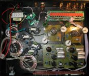
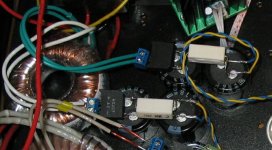
I used PCB for this preamp and also tried peer2peer version, but I have problems, both versions have hum, a lot of hum! Has anyone build it?
I built Frank's preamp, according to this schematic
using this power supply
http://www.the-planet.org/6GV8.html
I used PCB for this preamp and also tried peer2peer version, but I have problems, both versions have hum, a lot of hum! Has anyone build it?
Attachments
Hi Buble_corp
I built the 12BH7A version, with regulated PS, and had no problems with hum. I recommend you to take a picture of the whole thing, and post it here. People can than help you much better!
a picture says a thousand words
Erik
I built the 12BH7A version, with regulated PS, and had no problems with hum. I recommend you to take a picture of the whole thing, and post it here. People can than help you much better!
a picture says a thousand words
Erik
buble_corp said:I used PCB for this preamp and also tried peer2peer version, but I have problems, both versions have hum, a lot of hum! Has anyone build it?
I see you're using 6H8C. Did you use AC heaters? I'm not 100% sure, but I think AC is a no-no for that tube, it's given me tons of problems with hum on another project.
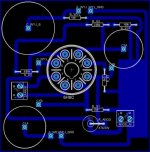
I'm still fighting with humm. Here it is a logical diagram of my pre. Currently, for debuging, I'm using one PSU and PRE board (single channel) as shown on diagram. I tried different ground setups, but without success. What is optimal grounding solution here?
Attachments
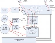
Well, let's see. You have twisted your DC heater wires, but not the AC from the transformers. You have used toroids which will couple mains-borne noise rather well. You have DC on your heaters, but I'm not clear if you have a regulator. You have ECL85 as your HT regulator, but it might have a heater/cathode problem. No mention of how you've done your earthing.
There's plenty of scope for hum here. If you haven't already done so, start by making a star earth at the input of the 6SN7 boards, and make sure there are no loops. Check that the 6SN7 heaters are referenced to 0V (even better, +40V). Is it 50Hz hum (electromagnetic induction), 100Hz (power supply hum), slightly buzzy 100Hz (capacitor ripple currents where they shouldn't be), or very buzzy 100Hz (transformer saturation)?
There's plenty of scope for hum here. If you haven't already done so, start by making a star earth at the input of the 6SN7 boards, and make sure there are no loops. Check that the 6SN7 heaters are referenced to 0V (even better, +40V). Is it 50Hz hum (electromagnetic induction), 100Hz (power supply hum), slightly buzzy 100Hz (capacitor ripple currents where they shouldn't be), or very buzzy 100Hz (transformer saturation)?
-> EC8010
Thanks for reply! Heaters are referenced to B+ ground by 82Ohm resistors on both pre and regulator board. Heaters are DC and filtered with CRC (C=10,000uF) not regulated. I will try to move main ground point from tube regulator to 6SN7 preamp input in evening. Thanks for suggestions. There are some symptoms that suggest ground wiring problem, i.e. when I close my hand to "hot" wire between output of RVC(volume attenuator) and input of 6SN7 pre humm is increasing, when I touch it humm(buzz) is loud. Humm/buzz slightly decreases when I touch case.
Considering sound, I think it isn't humm it's rather buzz (like ground loop buzz) I think that I should check if there is any connection between ground and case.
- Home
- Amplifiers
- Tubes / Valves
- Frank's Ultimate Tube Preamp