The ADJ capacitor slows down the rise of the output voltage, which reduces the charging current through the output decoupling capacitor. The diodes are for shutdown rather than start up.
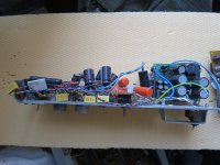
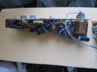
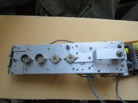
As i had to supply a Luxman CL-34 clone working at 390v dc, I took the decision to scrap the iron and the regulators and make good use of the 12v supply for fillaments i got from a semi-resonant SONY ps-2 smps and Dave on highvoltageforum helped me with a fantastic ZVS inverter that works really well with very high efficiency and no start-up problems:
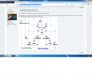
Baxandall converter strange output
For a month i was very happy to wind all sorts of ferrite transformers finding the best way to wire and fire it up. My last schematic was just a simple inverter from 12 to 100v dc based on Dave's circuit , followed by a voltage quadrupler that makes the start-up process fail proof .The inverter is big because i used 450vdc capacitors and 1200v dc ultrafast diodes...but it could be a quarter of its size with normaly rated components(160vdc caps and 200v diodes) or even smaller if all the voltage gets done from the transformer winding and only one filtercapacitor is used, but i almost always use voltage multipliers with low noise circuits no matter if low frequency or high as i find them lower noise and more forgiving with sudden unexpected loads during trials. Also logic level bss295(driver) and IRFZ46 transistors.My load is about 22ma idle current at 390v dc.
My first trials were simple bipolar Baxandal like inverters based on ztx1051a and ztx1055a but 22ma were a bit too much for a pair of ztx1055a as they got hot pretty quickly.
Baxandall oscillator vs Royer
Attachments

Last edited:
The ADJ capacitor slows down the rise of the output voltage, which reduces the charging current through the output decoupling capacitor. The diodes are for shutdown rather than start up.
Ah, I see. Thanks.
So, if the ADJ to GND cap slows down the rise of the output voltage, then adding a resistor in series to that cap would slow down its charging a little more, correct?
If that's correct, then it would reduce the charging current through the output decoupling capacitor.
And if that's correct, then putting a small resistance in series with the output decoupling capacitor would slow down that cap's charging time as well.
It's common practice to put a 2.7R resistor in series with the film cap on the output of the LM317. Morgan Jones puts 100R in series with that ADJ to GND cap in his "Valve Amplfiers 3rd Edition" (pg 360).
Perhaps these tricks can be applied to LR8 as well...
As jackinnj mentioned and I learned the hard way, an LM317 can become unstable when the output decoupling capacitor has too little effective series resistance. One solution is to use a run-of-the-mill aluminium electrolytic capacitor, another is to put a resistor in series with the capacitor.
Unfortunately there is nothing about ESR in the LR8 datasheet, while Salas's post #57 indicates that it does matter for the LR8 as well.
Regarding Cadj, the main effect of a small resistor Rcadj in series with Cadj is that initially at start-up when Cadj is still empty, the voltage will jump from 0 to (1 + (Rcadj in parallel with R21)/R20) Vref instead of 0 to Vref.
Last edited:
As jackinnj mentioned and I learned the hard way, an LM317 can become unstable when the output decoupling capacitor has too little effective series resistance. One solution is to use a run-of-the-mill aluminum electrolytic capacitor, another is to put a resistor in series with the capacitor.
That is the solution I used in the T-reg high voltage regulator. A 600V electrolytic of, say 10uF with some ESR is rather large, almost as large as the rest of the board, IF you can get them!
I settled for a 1uF film cap in series with a small 2 ohms resistor, and Bob's your uncle.
One reason for the relaxed cap requirement of just 1uF on the LR8 output may have to do with the usual high output voltage, which means that the feedback divider has a large ratio which lowers the loop gain. A (much) lower loop gain makes instability a lesser problem. It would be of interest to check whether an LR8 with say 12V output is still stable with 1uF.
The T-reg regulator is designed such that the loop gain does not vary with output voltage so stability is independent of output voltage.
Jan
Last edited:
It should be, as there are 5 V and 1.2 V regulator application circuits in its datasheet, all using 1 uF. By the way, with decoupled ADJ, you also have complete feedback.
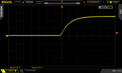
For your information I run some experiments at 25V input, 12.4V output. 2.2k 20k (nominal values) voltage setting divider. Cin (decoupling) 1uF MKT. Load was about 5mA to a resistor. What I saw:
1. Without any Cout its prone to instability when probing the output with the DMM leads.
2. Cout either 1uF MKT or various lytics stabilize it the same. I tried up to 47uF polar.
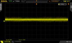
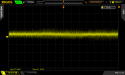
3. Cadj works, makes noise look smoother (20MHz BW). Tiny difference between 1-10uF.
4. At >10mA loading my LR8 starts limiting the output voltage.
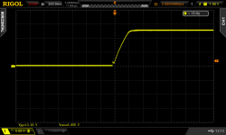
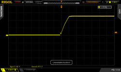
Screen captures:
Startup pics are for no Cadj then 1uF then 10uF. Noise pics are for no Cadj then 10uF.
1. Without any Cout its prone to instability when probing the output with the DMM leads.
2. Cout either 1uF MKT or various lytics stabilize it the same. I tried up to 47uF polar.
3. Cadj works, makes noise look smoother (20MHz BW). Tiny difference between 1-10uF.
4. At >10mA loading my LR8 starts limiting the output voltage.
Screen captures:
Startup pics are for no Cadj then 1uF then 10uF. Noise pics are for no Cadj then 10uF.
Attachments
Very interesting!
Regarding Cadj, with 2.2 kohm between output and ADJ, 1 uF Cadj gives you unity noise gain from about 72.3 Hz onwards and 10 uF from 7.23 Hz onwards. It's logical that you won't notice that difference when you measure over the full regulator bandwidth.
Regarding Cadj, with 2.2 kohm between output and ADJ, 1 uF Cadj gives you unity noise gain from about 72.3 Hz onwards and 10 uF from 7.23 Hz onwards. It's logical that you won't notice that difference when you measure over the full regulator bandwidth.
Yes, I know. It was just about quick visual clues over the scope's 20MHz bandwidth limit mode. Still a huge BW compared to audio.
In HV applications it will take time to reach target Vout with Cadj though. To charge climb all that high voltage. See it as a soft start function on the other hand.
It went into protection mode one time by the way. Something probably touched something else on the breadboard as I was handling it live. I had to power cycle it for reset. But it wasn't hot to the touch.
Definitely. With rongon's resistances and 10 uF, the voltage will settle with a time constant around 2.2 s, so it will take about 10 seconds until the output has settled within 1 %.
Not sure if it needs ESR in Cout, just wondering because most do.
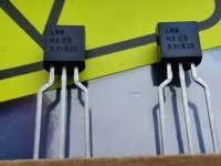
Anyways, I found four TO-92 samples I had in a drawer and I will breadboard in low voltage to check stability both with film and electrolytic 1uF caps to inform you guys.
Spectacular. Very generous of you. Thanks Salas.
Last edited:
So, some (hopefully not too dumb) questions:
1) For Cin, what are the penalties for using an electrolytic capacitor of about 10 to 33 uF? Will that zap the IC?
2) Would there be any benefit to adding a little resistance in series with Cout? Perhaps 3.3 ohms?
3) In those last two noise pics, I don't see any difference. What am I missing?
That sounds like a good thing to me.
EDIT TO ADD:
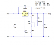
Attached schematic of LR8 with add'l caps, diodes, resistors. Does it look correct?
1) For Cin, what are the penalties for using an electrolytic capacitor of about 10 to 33 uF? Will that zap the IC?
2) Would there be any benefit to adding a little resistance in series with Cout? Perhaps 3.3 ohms?
3) In those last two noise pics, I don't see any difference. What am I missing?
In HV applications it will take time to reach target Vout with Cadj though. To charge climb all that high voltage. See it as a soft start function on the other hand.
That sounds like a good thing to me.
EDIT TO ADD:
Attached schematic of LR8 with add'l caps, diodes, resistors. Does it look correct?
Attachments
Last edited:
1. Small value film decouples best because its a fast cap. I don't think that a higher value electrolytic will zap it. But I did not run HV tests, you will see better in the HV domain.
2. It would do no harm at least as things suggest up to now.
3. The first one without Cadj has a wiggle pattern in it if you look closer. The next one with Cadj cap looks smooth. Its does not look like a very low noise reg in general. But don't trust quick indicative tests on a breadboard for characterizing a part. Most of it should be bench noise.
EDIT TO ADD:
Attached schematic of LR8 with add'l caps, diodes, resistors. Does it look correct?
Only calculate dissipation in the big value resistors of the voltage dividers to use proper wattage for them (3X nominal of what is electrically burned is usually long term safe).
Yes, thanks. In the circuit I built, there's 308V at the OUT pin, R1 = 820R, R2 = 220k.
I figure 308V/220k = 1.4mA, and 308V*0.0014A = 0.462W, so I used a big 2W metal film resistor for R2 (220k). It runs only slightly warm.
I figure 308V/220k = 1.4mA, and 308V*0.0014A = 0.462W, so I used a big 2W metal film resistor for R2 (220k). It runs only slightly warm.
Attachments
Last edited:
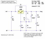
I swapped out the necessary resistors and capacitors on the audio PCBs, to try to tame that subsonic resonance. R18 is now 43k, Rp is 4.7k. C3 is reduced to 0.1uF. The rest stayed as was.
I also wired up the LR8 circuit pictured in the last post, on the existing LR8 PCB. It's ugly, with a couple of 10uF 450V electrolytics tack soldered onto the resistors connected to the LR8 ADJ pin and to GND. I'm pretty sure I wired it up correctly.
I couldn't fit a 1uF cap for C1, so I had to use a 0.22uF 400V. I hope that's enough capacitance to decouple the IN pin. Both C2 and C3 are 10uF. I used a BYW 600V damper diode for D2, because I ran out of 1N4004 and 1N4007.
I'll give it a double-check tomorrow, to make sure I didn't make any wiring errors. Then I'll be ready to reinstall it and fire up the preamp for another smoke test.
--
Back to questions about stabilizing and improving the LR8 regulator.
What issues can arise from using too large a value of capacitance from the ADJ pin to GND?
I've wired up the LR8 PCB with a 0.22uF 400V cap bypassing the IN pin, a 10uF 450V electrolytic bypassing the OUT pin, and a 10uF 450V electrolytic bypassing the ADJ pin.
There is a diode from the IN to OUT pins (cathode to IN). I added a diode from ADJ to OUT pins (cathode to OUT).
Do those changes make sense? Any mistakes there?
I'm about to wire it back up and fire up the preamp.
--
Well, that didn't work. Both LR8s are outputting 110VDC. They probably both went into thermal shutdown.
I'm going to remove the ADJ to GND capacitors (10uF 450V). I suppose I can leave the protection diodes going from ADJ to OUT.
What could happen if I remove the ADJ-GND caps but leave the 10uF caps OUT-GND? Will the OUT-GND caps draw too much current and put the LR8s into protect mode?
I'm going to remove the ADJ to GND capacitors (10uF 450V). I suppose I can leave the protection diodes going from ADJ to OUT.
What could happen if I remove the ADJ-GND caps but leave the 10uF caps OUT-GND? Will the OUT-GND caps draw too much current and put the LR8s into protect mode?
- Home
- Amplifiers
- Tubes / Valves
- For RIAA preamp: Large value caps vs. Regulated/Stabilized PSU