Very well put @rongon
Reckoning this is a very interesting topic, so far a lot of interesting points have been discussed and cues given, I will be in a similar situation soon.. following this, but cannot contribute as I am a novice I'm afraid.
Reckoning this is a very interesting topic, so far a lot of interesting points have been discussed and cues given, I will be in a similar situation soon.. following this, but cannot contribute as I am a novice I'm afraid.
Radiotron 4th suggests this R be 20%-30% of the plate resistor. Which is indeed 25k-37k, or what you say.
I shudder when I see people put 1k or less to decouple a single 12AX7. What is the point? What is the need?? If this is the first stage in a multi-stage amp, you can't even need a big signal, so high B+ is only marginal benefit.
You are quite right. I was trying to get closer to 1mA plate current going through the first stage 12AX7 believing that would somehow 'sound better'. Of course, any benefit from that is nothing compared to the drawback of that subsonic resonance. This one's a hard lesson. My punishment will be removing the two audio PCBs and reworking them *again*.
In this particular circuit, it looks like a higher B+ is beneficial for the second stage, since that's closer to line level and may need to swing more volts. It also looks like that's where most of the distortion happens, and I'm concerned about the second stage possibly blocking on big pops and clicks.
But of course the first stage will never see enough signal to clip or block. 200mV max from the highest output cart and worst possible click or pop, right?
A good lesson to learn here.
@geoturbo - I consider myself a novice too. It's when I try to do something clever that I get into trouble!
Calling all moderators... Can I ask a favor?

Done, but only because I chanced on reading this, remember the procedure for any request is press the report triangle under the relative post and write about it in the message box. This way it goes through the official pipeline of mods task list for evaluation.
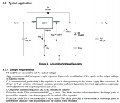
I wonder if the inrush current you get due to Cp and C10 triggers the protection. If so, a capacitor across R21 (with a protection diode to the LR8's input) might help it starting up as well as suppress its noise.
Across R20 to output maybe? That's how its practiced in LM317 at least.
"Protection diode D2 is recommended if CADJ is used.The diode provides a low-impedance discharge path to prevent the capacitor from discharging into the output of the regulator."
Attachments
I prefer "passive" C-R-C filtering of phono B+. I used flash electrolytic capacitors:
Preamplifier PSU
Preamplifier PSU 2
Preamplifier PSU
Preamplifier PSU 2
Thanks everyone for the ongoing comments, and thanks Salas for the moderator intervention (and now I know what the purpose of the red triangle thingie is!).
I have a couple of tasks in front of me. First, I need to replace R18 with a much larger value part. I have some 20k 1/2W metal film resistors. I figure the 12AX7 is going to draw only about 750uA of plate current, so...
20,000 ohms * 0.00075A = 15V
15V * 0.00075A = 0.011W
I think a 1/2 watt metal film resistor should be fine for R18. Yes? No?
Across R20 to output maybe? That's how its practiced in LM317 at least.
"Protection diode D2 is recommended if CADJ is used.The diode provides a low-impedance discharge path to prevent the capacitor from discharging into the output of the regulator."
Good point, thanks for the correction. It's likely that the output will temporarily be at the lowest potential when everything is powered down, so then the diode can best go to the output.
Is this the correct way to implement the reference noise filtering capacitor and the protection diode "D2" from LR8 ADJ to OUT?
The protection diode is labeled D6 in the attached schematic.
Reference noise filtering cap is C16.
R22 (10R) is added because it seems to be standard practice.
--
The protection diode is labeled D6 in the attached schematic.
Reference noise filtering cap is C16.
R22 (10R) is added because it seems to be standard practice.
--
Attachments

I prefer "passive" C-R-C filtering of phono B+. I used flash electrolytic capacitors:
Preamplifier PSU
Preamplifier PSU 2
It would be so easy for me to rig up a CRC filter between the raw B+ PCB (345V) and the audio PCBs (which each have their own RCRC onboard). I have enough B+ voltage available to afford dropping 10V or so, and I have a bunch of 800uF 330V electrolytic caps that will be easy enough to fit inside the chassis. 10V/0.015A = 666.67 ohms, so 620R 1W would be quite adequate. I even have a couple of old Stancor 7H 50mA (550 ohms DCR) chokes I could use. That would kill all ripple. It would be so easy to do...
Is this the correct way to implement the reference noise filtering capacitor and the protection diode "D2" from LR8 ADJ to OUT?
The protection diode is labeled D6 in the attached schematic.
Reference noise filtering cap is C16.
R22 (10R) is added because it seems to be standard practice.
--
Yes, I think it is. I don't know what R22 is meant for, but it won't harm as long as it is << R20.
LM317 -- 100uF Aluminum Electrolytic on the output, a 1uF film cap will render the regulator unstable.
True, but 1 uF is the recommended value for an LR8.
Just looked it up: 1 uF is the minimum recommended value for an LR8, the datasheet doesn't recommend any specific type of capacitor.
Just looked it up: 1 uF is the minimum recommended value for an LR8, the datasheet doesn't recommend any specific type of capacitor.
Last edited:
Just looked it up: 1 uF is the minimum recommended value for an LR8
(Thanks for this.)
Hmmm.... Should I put a 10uF electrolytic there?
I read the LR8 data sheet a while ago and it looks like I misunderstood that 1uF was the maximum recommended capacitance. I was wrong. (Oh man...)
"To maintain stability, a bypass capacitor of 1.0μF or larger and a minimum DC output current of 500μA are required."
OK, that's one more thing to change!
Last edited:
Still, the example schematics in the datasheet almost all show capacitors of nominally 1 uF, so I guess they took some safety margin for capacitor tolerances to ensure that 1 uF nominal will work.
won't a 10 uf cap trip the regulator at start-up?i'm thinking of the "bennefits" of a 10ma regulator upper surge limit...
Oops, just saw the last two posts addressing the output cap on the LR8. I'll leave them at 1uF for the time being. In simulation, putting 10uF there doesn't do very much.
--
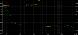
Meanwhile, auditioning the preamp yesterday, I had trouble with motorboating. Obviously there's a low frequency instability.
I can't figure out how to do a spectrum analysis display on my Rigol scope, but I do see problems in the subsonic regions. So I went back to LTspice and tried to replicate the issue there. It didn't take me long to figure out what the problem is.
I had designed the circuit to play down to 20Hz driving a relatively heavy load of 10k ohms (typical input impedance of a class D amp or similar). What I didn't count on was that into a 100k or higher impedance load, the preamp makes a huge (+14dB!!!) boost right around 1Hz 😱😱😱: !!!
The first image attachment is the frequency response of the existing preamp circuit into a 1M ohm load.
OK, I need to fix that. Obviously.
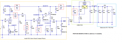
I had to juggle several things to get that resonance under control, maintain low audio frequency response, and minimize the amount of parts transplants I'll need to do. I think I've succeeded. The second image attachment is the newly updated schematic. The updated parts values are shown with "****".
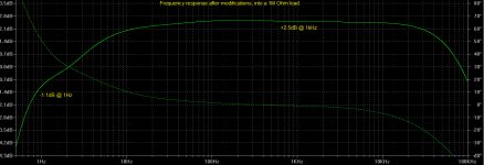
The third image attachment is the predicted frequency response into a 1M load, after the changes. There's still a shelf where the response stops rolling off below 10Hz, but it's several dB below the response in the audio band. I think (hope) it'll be OK. Of course, into a heavier load the low frequency response rolls off more quickly.
The changes are:
C3 - originally 0.22uF, now 0.1uF
R18 - originally 4.7k, now 43k 1/2W metal film
R9 - originally 1.43k, now 1k (only makes a minor difference)
R12 - originally 1.5k, now 2k (to keep the cathode 1.5V above the grid)
Rp - originally 1k, now 2.2k 1/2W metal film
C15 - originally 1uF, now 10uF 400V electrolytic
The first stage 12AX7 is now run on the lean side, with only about 650uA of plate current. But that's commonly done with 12AX7, so I hope it will be OK.
The second stage 12AX7 also runs leaner, at about 750uA plate current.
The source follower MOSFET runs at 5.5mA drain current. I understand that MOSFET devices typically have rising gate capacitance when run at less than 5mA Ids.
I hope to be able to get these parts swapped this evening.
--
--
Meanwhile, auditioning the preamp yesterday, I had trouble with motorboating. Obviously there's a low frequency instability.
I can't figure out how to do a spectrum analysis display on my Rigol scope, but I do see problems in the subsonic regions. So I went back to LTspice and tried to replicate the issue there. It didn't take me long to figure out what the problem is.
I had designed the circuit to play down to 20Hz driving a relatively heavy load of 10k ohms (typical input impedance of a class D amp or similar). What I didn't count on was that into a 100k or higher impedance load, the preamp makes a huge (+14dB!!!) boost right around 1Hz 😱😱😱: !!!
The first image attachment is the frequency response of the existing preamp circuit into a 1M ohm load.
OK, I need to fix that. Obviously.
I had to juggle several things to get that resonance under control, maintain low audio frequency response, and minimize the amount of parts transplants I'll need to do. I think I've succeeded. The second image attachment is the newly updated schematic. The updated parts values are shown with "****".
The third image attachment is the predicted frequency response into a 1M load, after the changes. There's still a shelf where the response stops rolling off below 10Hz, but it's several dB below the response in the audio band. I think (hope) it'll be OK. Of course, into a heavier load the low frequency response rolls off more quickly.
The changes are:
C3 - originally 0.22uF, now 0.1uF
R18 - originally 4.7k, now 43k 1/2W metal film
R9 - originally 1.43k, now 1k (only makes a minor difference)
R12 - originally 1.5k, now 2k (to keep the cathode 1.5V above the grid)
Rp - originally 1k, now 2.2k 1/2W metal film
C15 - originally 1uF, now 10uF 400V electrolytic
The first stage 12AX7 is now run on the lean side, with only about 650uA of plate current. But that's commonly done with 12AX7, so I hope it will be OK.
The second stage 12AX7 also runs leaner, at about 750uA plate current.
The source follower MOSFET runs at 5.5mA drain current. I understand that MOSFET devices typically have rising gate capacitance when run at less than 5mA Ids.
I hope to be able to get these parts swapped this evening.
--
Attachments
Last edited:
won't a 10 uf cap trip the regulator at start-up?i'm thinking of the "bennefits" of a 10ma regulator upper surge limit...
The datasheet is not informative enough, it takes some practical tests to conclude what it likes best. No word from the manufacturer about Cadj, if its even permitted or not, no word about if any ESR is needed or not in the output cap. LR8 has a reputation of being quirky on top of that.
won't a 10 uf cap trip the regulator at start-up?i'm thinking of the "bennefits" of a 10ma regulator upper surge limit...
It might, but not when there is another 10 uF across the resistor from ADJ to ground.
That seems a curious way to negate the hard-won clean output of a clean regulator. The 100R creates current-induced signal ripple, which the final cap has to try to get rid of again.
While at the reg output, all is clean and does not vary with signal current.
The diyaudio store has a suitable regulator kit.
Jan
Ideally, actually, a current clamp instead of 100 Ω would be much better, answering your valid objection, and still accomplishing what was originally desired.
Well, sort of.
The 'other function' of the R+C final stage is to act as a cheap, clean post-regulation noise-of-regulation quench. I've noticed a substantial amount of 'but-but-but-regulators-introduce-noise'; the RC addresses that without very much PS wobble at the valve current levels and fluctuations expected in most amps.
Still, the use of a simple current clamp has applicability, if noise is no real consideration.
Heck… it doesn't even much matter whether the current clamp is on the input or output side of the regulator, for that. And a depletion mode device such as IXTP1R6N50D2 would fill the bill, nicely, for $3/ea in small quantities.
⋅-⋅-⋅ Just saying, ⋅-⋅-⋅
⋅-=≡ GoatGuy ✓ ≡=-⋅
It might, but not when there is another 10 uF across the resistor from ADJ to ground.
I don't understand what the one has to do with the other.
As I understand it, the capacitor from ADJ to GND draws current while charging at start-up, so a protection diode becomes necessary from ADJ to OUT.
The 10uF cap from OUT to GND will also draw current at start-up, drawing current through the LR8, possibly causing it to shut down to protect itself.
How would one cap charging up at start-up counteract the other cap charging up at start-up?
--
- Home
- Amplifiers
- Tubes / Valves
- For RIAA preamp: Large value caps vs. Regulated/Stabilized PSU