Removed the ADJ-GND caps.
Now the LR8s are putting out 130VDC. Still not right.
Oh well. This has been far too much trouble. The way they worked was with a small value cap (1uF) bypassing OUT and a large value cap bypassing IN (100uF). Bass-ackwards, I know. But it worked.
I think I'm going to rig up a simple RC decoupling/filter so I can get reasonably ripple-free DC to the audio boards and make sure they aren't fried.
Last edited:
It might not like trying to charge a large cap on it's output and do into protection from the inrush?
Thanks for starting this thread BTW. I'm going to try the TL783 idea for my RIAA since it needs ~50mA.
Thanks for starting this thread BTW. I'm going to try the TL783 idea for my RIAA since it needs ~50mA.
Weak and quirky in Rongon's situation, maybe more purposeful if augmented with a pass NPN or NMOS. To can deliver some useful current peaks. Tried with MJE3055T and IRF640 in low voltage, they work there. In HV maybe there will be surprises again. Better the BJT in LV because VGS loss is too much comparatively.
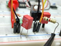
Collector to Vin, base to LR8 out, emitter to the load (that bigger 1k resistor). I used 1uF Wima Cadj and another one for Cout parallel to the load.
Collector to Vin, base to LR8 out, emitter to the load (that bigger 1k resistor). I used 1uF Wima Cadj and another one for Cout parallel to the load.
Attachments
I've seen some regulator designs using the LR8 as the regulator IC (sort of Maida style) in a high voltage-low current bubble, with a larger MOSFET or BJT as a pass device. I didn't want to go that route because the Maida style regulators work fine and are well documented, and I was hoping for a single chip solution. Oh well. That was not to be.
I replaced the LR8 PCB with a single 2.2k 2W resistor and 100uF capacitor. The preamp noise floor is now much quieter, especially in regards to hiss. There was noticeable hiss with the LR8, but now there's no hiss at all with a pair of RCA 7025 pulls in the preamp. I mean like zero hiss. There's no hum either until I crank it to 11, and this thing has a lot of gain too (should be about 47dB).
The reason I was looking at a regulated supply was that I thought I wouldn't have high enough voltage to be able to filter ripple out with RC stages. It turns out that the nominally 500VCT 40mA transformer I'm using is delivering much higher voltage than that. The whole shared PSU is 47uF-470R-150uF-2.2k-100uF, delivering 385VDC of B+. Each audio PCB then has its own RCRC of 4.7k-100uF-43k-33uF.
It's too late at night to play records right now, but I've got the preamp powered up to burn in. I'm switching to its output now and again to make sure it's stable and hasn't started to make noises. So far so good.
So to sum up, and to answer my original question:
1) The LR8 is too difficult to work with for a single-chip solution, even for output of 310V with 7mA load.
2) The LR8 is only stable with very small cap values on it, and its output is noisy. It injected a pretty good amount of hiss into this circuit.
3) As for the question of regulated vs. passive decoupling/filtering, it seems that for me the passive solution is winning right now. Easy to implement because large value electrolytic caps are cheap. Does it sound good? Now that I heard the preamp with the LR8 regs working (and I liked the sound of that), I'll have to try it this way for a day and see how it compares.
---
Last edited:
*Maida is actually keeping the HV out of an LM317T reg which has the ability to deliver many mA on its own. On the other hand just using a powerful current pass element over LR8 it does not shield it from HV. Lower parts count yes, but I am not sure if our friend LR8 will behave itself.
Whatever works best for you in the end.
True.
My plan at this point is to use this as a sort of test bed for different types of B+ supplies. Since both channels of audio circuits draw only 15mA total, I won't have to use big heatsinks anywhere. That means I can try a Maida on a little tagboard and pop it in there, or a zener follower, or a Morgan Jones-style Statistical Regulator, and so on.
It will be interesting to be able to compare the 'sound' of each different power supply topology with this phono preamp circuit as the constant.
At least that's the plan.
--
There is no recommended value for the input decoupling in either the datasheet or this application note http://ww1.microchip.com/downloads/en/AppNotes/AN-H40.pdf (except for an equation stating that the supply buffer cap should be large enough to keep it out of dropout). Do you see any signs of oscillation?
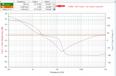
What is interesting in the application note is the graph that shows it can only deliver 2 mA when the voltage between input and output is 300 V, unless it is for such a short time that it has no chance to get hot. Unfortunately.the thermal time constant isn't shown.
What is interesting in the application note is the graph that shows it can only deliver 2 mA when the voltage between input and output is 300 V, unless it is for such a short time that it has no chance to get hot. Unfortunately.the thermal time constant isn't shown.
Last edited:
I'm sorry, I got frustrated and removed the LR8s. The PCB has very small through holes so is extremely aggravating to rework. I've been hacking away at it to the point where some traces are beginning to come loose. With an IC as touchy as an LR8 I figure that board is no longer useful.
It's annoying that the data sheet provides so little guidance on decoupling/compensation C's and/or R's. Frustrating.
I figure if the LR8 is too noisy (high freq hiss, etc) to be used to supply high gain 12AX7 circuits (like RCA style phono stage) without additional decoupling/filtering -AND- it's unstable if bypassed with 10uF of capacitance from its ADJ and OUT pins, then it's probably not worth pursuing any more. Limited rewards to be had for all this fussing and waste of parts.
Last edited:
Well... the new "true engineering" concept evolved nowadays into a phylosophy of designing circuits only able to work for a maximum of 3 years...and the old golden rule was that a power supply needed to withstand at least twice the maximum required power, but in the 70's, 4 times the max needed power was the rule..Dealing with tubes it would be a shame to apply phone charger design rules just to proove you're a hell of a designer oriented on maximum efficiency.
Wow, this project has been a bear for me.
- Originally chosen (vintage) transformer was dead. I had to disconnect and remove it, drill new holes to fit the new transformer, and install/connect the new one. Fortunately, the new one worked like new. LOL - Never trust vintage iron.
- I got it working, but I had problems with one channel motorboating, and some 12AX7s making obnoxious burping and popping noises. I determined that with the RC decoupling values I'd chosen, there was a huge resonance in the power supply feeds, down at about 1 to 2 Hz (!!!). Very bad. So, I pulled the audio PCBs and increased the values of the decoupling network resistors to lower the F3 of their respective RC filters, and decreased the value of the coupling cap after the first stage from 0.22uF to 0.1uF, to reduce the likelihood of more subsonic problems.
- Now after all that reworking of the audio boards, I hooked up the preamp and powered it up to finally listen to it. All was good for a while (and it sounded really nice) but the LR8s would shut down if I turned the preamp off and then on too quickly. Sometimes one channel's LR8 would shut down and the other would stay on. Frustrating, so I embarked on 'improving' the LR8 regulators with additional caps for filtering/decoupling, with the additional protect diode required. The PCB turned out to be poorly designed for reworking, with pads that were too small for easy desoldering. It was a mess, and I managed to lift a trace and badly damage a couple of pads. It wasn't so bad that I couldn't wire it up, but it was a real pain. Then, after all that, both LR8s refused to fully wake up and allow full voltage through. I pulled that board out and threw it away. Very frustrating.
- Finally, I decided to play it safe and swap in another stage of RC decoupling in place of the regulators. I used good ol' Ohm's Law to try to get the voltage I wanted. 2.2k and 100uF. Meanwhile, on the raw B+ PSU, the CRC immediately after the rectifier diodes included a resistor of only 470R, which drops only about 7V at 15mA load. That choice would come back to haunt me...
- With the light load (15mA), it became clear that the transformer's regulation is not so good. It's rated at 500VCT 40mA, but with the 15mA load it's giving 580VCT (!). My raw B+ went way high to +375, and I think the right channel MOSFET source follower went crazy. Once the preamp warms up, that MOSFET's current draw slowly rises and rises, until it's drawing over 10mA, while the audio from that channel mutes. (Weird.)
- I went back in to remove the raw B+ PSU so I could replace that 470R with 2.2k ohms (3W metal oxide). That brought the raw B+ down to +345V, which is much safer for the downstream circuitry. The audio PCBs see +315V, which was the original voltage going to them from the LR8s. I fired up the preamp again, but the right side still mutes. The MOSFET must have gotten fried just enough to go crazy.
I'm now working on replacing the source follower MOSFETs, and this time I'll place clip-on heatsinks even though the MOSFETs dissipate only 800mW each in operation. I really hope I've figured out all the problems. This has been a real journey.
If everything works, I'll start thinking about what kind of regulator I'll want to use as the permanent solution.
Wish me luck!
--
Last edited:
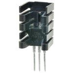
If you have some of these - I'd use them. 10pcs/lot Black Aluminum 21*15*11mm TO 220 TO220 heatsink radiator for MOS,7805 Triode Transistors Cooler IC Chip dissipation|heatsink radiator|to220 heatsinkaluminum heatsink radiator - AliExpress
Which MOSFET are you using again?
Which MOSFET are you using again?
I have a small collection. I could use ZVN0545 (TO92 case), which would be the lowest capacitance choice. I'd have to raise the value of its source load resistors to something like 47k or 56k though. I don't want to do that.
I'm currently using FQPF2N70. They're in the TO220FP case, so have a plastic covered tab, not live metal. They're not as low capacitance as ZVN0545 but are low enough, and they're more robust. Just not robust enough to survive my ham-handedness! LOL
I have a bunch of clip-on sinks like the one in the picture below...
Attachments
Last edited:

The way I had the MOSFETs biased, I actually don't need to heatsink them. A TO220FP case is good for up to about 1W Pdiss. However, when I swapped in the passive RC, I misjudged the voltage drop, and the audio PCBs got over-voltaged a bit. The caps and resistors are all over-rated enough to withstand that, but the MOSFET dissipated right about 1W for a bit. I'm sure that's what fried it. Now that I increased the resistance of the first PSU CRC, the MOSFETs are dissipating 800mW. That's low enough to work without a heatsink, but I've learned my lesson. Always put heatsinks on TO220 devices!!!!
True, but 1 uF is the recommended value for an LR8.
Just looked it up: 1 uF is the minimum recommended value for an LR8, the datasheet doesn't recommend any specific type of capacitor.
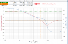
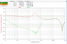
I ran some tests on the LR8N3 with a 30 Volt output, 7mA load, 42 degrees of phase margin with 1uF ASC film cap @2.3kHz, and 62 degrees at 32kHz.
Attachments
Wow, this project has been a bear for me.
- Originally chosen (vintage) transformer was dead. I had to disconnect and remove it, drill new holes to fit the new transformer, and install/connect the new one. Fortunately, the new one worked like new. LOL - Never trust vintage iron.
- I got it working, but I had problems with one channel motorboating, and some 12AX7s making obnoxious burping and popping noises. I determined that with the RC decoupling values I'd chosen, there was a huge resonance in the power supply feeds, down at about 1 to 2 Hz (!!!). Very bad. So, I pulled the audio PCBs and increased the values of the decoupling network resistors to lower the F3 of their respective RC filters, and decreased the value of the coupling cap after the first stage from 0.22uF to 0.1uF, to reduce the likelihood of more subsonic problems.
- Now after all that reworking of the audio boards, I hooked up the preamp and powered it up to finally listen to it. All was good for a while (and it sounded really nice) but the LR8s would shut down if I turned the preamp off and then on too quickly. Sometimes one channel's LR8 would shut down and the other would stay on. Frustrating, so I embarked on 'improving' the LR8 regulators with additional caps for filtering/decoupling, with the additional protect diode required. The PCB turned out to be poorly designed for reworking, with pads that were too small for easy desoldering. It was a mess, and I managed to lift a trace and badly damage a couple of pads. It wasn't so bad that I couldn't wire it up, but it was a real pain. Then, after all that, both LR8s refused to fully wake up and allow full voltage through. I pulled that board out and threw it away. Very frustrating.
- Finally, I decided to play it safe and swap in another stage of RC decoupling in place of the regulators. I used good ol' Ohm's Law to try to get the voltage I wanted. 2.2k and 100uF. Meanwhile, on the raw B+ PSU, the CRC immediately after the rectifier diodes included a resistor of only 470R, which drops only about 7V at 15mA load. That choice would come back to haunt me...
- With the light load (15mA), it became clear that the transformer's regulation is not so good. It's rated at 500VCT 40mA, but with the 15mA load it's giving 580VCT (!). My raw B+ went way high to +375, and I think the right channel MOSFET source follower went crazy. Once the preamp warms up, that MOSFET's current draw slowly rises and rises, until it's drawing over 10mA, while the audio from that channel mutes. (Weird.)
- I went back in to remove the raw B+ PSU so I could replace that 470R with 2.2k ohms (3W metal oxide). That brought the raw B+ down to +345V, which is much safer for the downstream circuitry. The audio PCBs see +315V, which was the original voltage going to them from the LR8s. I fired up the preamp again, but the right side still mutes. The MOSFET must have gotten fried just enough to go crazy.
I'm now working on replacing the source follower MOSFETs, and this time I'll place clip-on heatsinks even though the MOSFETs dissipate only 800mW each in operation. I really hope I've figured out all the problems. This has been a real journey.
If everything works, I'll start thinking about what kind of regulator I'll want to use as the permanent solution.
Wish me luck!
--
I'm not going to say I told you, but you really should have gotten a T-reg and be done 😎
Jan
Tant pis, it's too wide to fit in this chassis layout. Oh well.
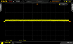
I ran some tests on the LR8N3 with a 30 Volt output, 7mA load, 42 degrees of phase margin with 1uF ASC film cap @2.3kHz, and 62 degrees at 32kHz.
Well, it doesn't look like there's much ripple suppression there.
What if the OUT bypass cap is 10uF?
What if the input voltage is +345V and the output is set to +315V?
The LR8 is rated for up to +400V out, but is it useful at those high voltages?
- Home
- Amplifiers
- Tubes / Valves
- For RIAA preamp: Large value caps vs. Regulated/Stabilized PSU