No, but it can be noisy like hell depending on what regulator you use. With a very low noise regulator, that RC filter makes no sense, with an ordinary regulator and a circuit with little PSRR, it suppresses most of the regulator noise.
Last edited:
In my opinion, the main disadvantage of a series regulator is that it produces noise, often quite a lot of it.
For completeness, it's the amplified voltage reference noise that normally dominates if it isn't filtered somehow. The same holds for a shunt regulator or a switched-mode regulator with the same type of reference if the reference isn't filtered. Low-noise regulators are usually regulators with a good low-pass filter between the reference and the rest.
Is that the purpose of the capacitor connecting from the regulator IC ADJ pin to ground?
Would the LR8N3 (the TO92 version) benefit from that capacitor? (I would think yes...)
If yes, what value capacitor would be safe (less likely to provoke the LR8 to shut itself down or get zapped)?
--
Would the LR8N3 (the TO92 version) benefit from that capacitor? (I would think yes...)
If yes, what value capacitor would be safe (less likely to provoke the LR8 to shut itself down or get zapped)?
--
Last edited:
What is your taste? Both approaches produce very different sound, so i cannot see how someone would enjoy both equally. Both approaches are also audibly compromised imo.
Interesting question! I've had good results with passive power supplies, but it seems the conventional wisdom is that it's absolutely necessary to use a regulated B+ for a phono stage. So I got the idea to try one LR8 per channel for this phono stage project.
Getting a passive supply to sound good is not easy, especially without good sounding chokes. Getting a regulator to sound good is a lot easier and there are ready made solutions, all of which based on shunt regulation. A combination of CLCLC + Salas seems to work for me, but there are those who find the sound too analytic and prefer no regulation.
Perhaps an LR8-based regulator is simply doomed to 'sound bad'(?).
In what way(s) will a plain old CRCRC network 'sound bad'? Why are chokes necessary? I have plenty of 400V rated electrolytic capacitors in stock. Is 'electrolytic capacitor sound' the issue?
--
I've been trying to use LTspice to guide me to a decision about this passive vs. regulated PSU question.
I have my built circuit in a sim.
To simulate post-rectification ripple, I added a 1.414V peak 120Hz sine wave in series with the DC voltage source, before the reservoir capacitor. Now I can plug in different power supply smoothing/regulator circuits to see what the ripple reduction looks like.
(I tested ripple levels by applying a 0.1mV 1kHz audio signal to the phono stage's input, observing the FFT of the output.)
I cannot find an LR8 model for use in LTspice, so I've substituted Bob Cordell's TL783 model. I know it's not the same thing, but it does appear to work in simulation. Perhaps the model ignores the real-life TL783 voltage limits, so can serve as a reasonably good stand-in for the LR8. Perhaps. So I tried it.
The results are dismaying. It appears the LR8 drops about 10V DC, as expected, but it does not appear to provide much ripple reduction. (??) I put a 10uF cap from the ADJ pin to ground, and that made practically no difference.
I went back and replaced the 33uF caps at the B+ input of each audio PCB with my last two 100uF 400V caps (in real life). In simulation that reduced the ripple from -69dB down to -80dB. That tells me that—at least in simulation—only the RC decoupling networks are providing ripple suppression, not the regulator IC.
What the heck?
Either the simulation is accurate and the LR8 does not provide much in the way of ripple reduction, or the simulation is not accurate and I'm running myself around in circles.
I have a bunch of brawny 800uF 330V electrolytic caps I can throw at this, so I simulated the circuit with no regulation, but an additional RC of 220R-800uF for the common B+. That drops the ripple to negligible levels. With the LR8 in circuit, 120Hz ripple appears to be only -69dB down. With the LR8 removed and the 220R-800uF RC decoupling network in its place, the ripple is practically removed (at least -92dB down).
I already drilled holes and only have room for one or the other, either the LR8 PCB or the 220R-800uF RC (the cap is physically large, but I can make it fit).
I'm very tempted to wimp out, stay in my comfort zone, and go with the all-passive psu with additional RC network.
Maybe I'll try it in real life with the LR8s (one per channel, loaded by 7mA each). If it doesn't work out, I'll swap in the RC network and call it a day.
We shall see...
Last edited:
I used TL783 for a few time this way:
Gyraf Audio - G9 DIY
Couldn't hear any noise...dead silent.You just need to make sure vin-vout=125v is not exceeded.
Gyraf Audio - G9 DIY
Couldn't hear any noise...dead silent.You just need to make sure vin-vout=125v is not exceeded.
Attachments
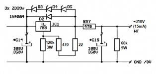
I think the problem in this particular application is that TL783 requires > 15mA load for it to regulate. This circuit draws about 15mA, so this would be marginal. I suppose I could add a bleeder resistor to draw another 5mA or so. I have a 60k wirewound resistor handy, but it would be dissipating 1.815W all the time (hot), and would need to be rated 5W or higher.
Like this? (see first attached diagram)
I see the three 39V zeners you have from OUT back to IN on the TL783. I don't think that would be necessary for an LR8, since it has a max voltage of over 400V, and I'm feeding it no more than 340V at its input. I do have a 1N4007 from OUT to IN.
So I'm basically doing the same thing as you did, but with the LR8N3 IC. I have one LR8 per channel, so each has a 7mA load (LR8 is rated at 10mA max). I expect to use it with approximately 325V in and 310V out. (See second attached diagram.)
If you had good results with the TL783, then I don't see why I shouldn't have equally good results with LR8. I'll try it...
--
Attachments

Last edited:
It has passed the Smoke Test.
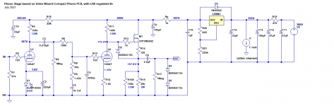
With 120VAC wall juice and with the tubes in their sockets and conducting, I'm getting +357VDC raw B+, which is higher than I expected. That's because the power transformer, which has a secondary rated at 500VCT from 117VAC, is delivering a measured 560VCT from 120VAC. That's OK!
The output from the LR8 regulators is +308VDC, which is just a bit lower than I expected.
The output from the heater regulator is exactly +12.6VDC.
Now to make sure it's stable and then to see if it's making horrible noises, before the audio test.
--
And, just like that... I popped something. I was taking voltages and one channel's cathode LED went dim. Now that channel's LR8 is outputting only 80VDC. Time for some troubleshooting. (Sigh.)
WAIT...
I powered it off, let it sit, powered it back on, and now all is well again. I must have tripped the LR8's protection and it needed to reset. Well, that's nice. I thought I had popped the silicon and would have to open everything up again to replace that channel's MOSFET and LR8. Fun with silicon.
Phew!
Last edited:
So finally, the question:
What would be the disadvantages of using a 'passive' PSU employing these monster 800uF capacitors as compared to something like a single LR8 per channel, or a Maida reg set at 310V?
I figure that the impedances of a 12AX7-based circuit are high (rp of about 75k ohms), so an ultra-low impedance PSU is not going to be all that beneficial, right?
--
FWIW here is a screen clip from the Morgan book... But nobody likes absolute statements like this, too many variables, but maybe for the DIY'er this is more true than not. A company like McIntosh that has unlimited brainpower and fabrication capabilities wouldn't have to live by an absolute like this when they can wind any choke they want, commission suppliers, etc. without blowing the budget.

Morgan is correct to a point, depends upon Zout of the regulator.
but regulators like the lm317, TL783 etc are not high gain devices and the error amplifier generates its own THD which is imparted on the supply rail. that's why you can hear transients like (cymbal, triangle, piano etc.) blur.
Elvee's "de noizer" increases the gain of the LM317...but I have not implemented it in HV.
Yup. I'm a big fan of Valve Amplifiers. I remember that passage.
That implies that the quality of the *regulator* is going to be audible from a single-ended amplifier circuit (and there's no more finicky single-ended than an unbalanced in/out phono stage, right?).
The question remains, if the LR8 is a 'bad' regulator, would it sound worse than a high capacitance (low impedance) CRCRC type of supply? And if yes, in what way(s)?
That's all academic now, I guess, because I have this circuit working now. The LR8 and MOSFET survived my bumbling perfectly well. I popped a 12AT7 in and listened put the preamp's output into a headphone amp and headphones to listen to its noise signature. The noise is entirely pink, more weighted towards lower frequencies. In headphones with nothing plugged into the inputs, there was zero hum, just 'tube rush' noise. So I decided to proceed to the full-on audio test.
I still have the 12AT7s in there, so I know the gain is lower than it will be with 12AX7s. However, I had designed this circuit to work with either 12AX7, 12AT7 or 12AY7.
Once in the system and powered up, If I crank the volume all the way up I can hear a bit of hum. At lower volume settings I can't hear any hum at all, but there is a little bit of hiss if I stick my ear into the speakers.
One thing I can say already is that I love the sound of vinyl playing through tubes. The mids sound somehow 'juicy'. I can't describe it, but it's an easier-going sound than what I was getting through the Hagerman Bugle. Less 'dry'? I don't know. All I can say is that I think I'll like having a tube phono stage again.
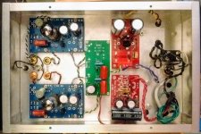
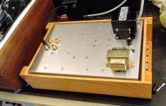
Here's the built circuit (attached). Let me know if you see any howlers.
That implies that the quality of the *regulator* is going to be audible from a single-ended amplifier circuit (and there's no more finicky single-ended than an unbalanced in/out phono stage, right?).
The question remains, if the LR8 is a 'bad' regulator, would it sound worse than a high capacitance (low impedance) CRCRC type of supply? And if yes, in what way(s)?
That's all academic now, I guess, because I have this circuit working now. The LR8 and MOSFET survived my bumbling perfectly well. I popped a 12AT7 in and listened put the preamp's output into a headphone amp and headphones to listen to its noise signature. The noise is entirely pink, more weighted towards lower frequencies. In headphones with nothing plugged into the inputs, there was zero hum, just 'tube rush' noise. So I decided to proceed to the full-on audio test.
I still have the 12AT7s in there, so I know the gain is lower than it will be with 12AX7s. However, I had designed this circuit to work with either 12AX7, 12AT7 or 12AY7.
Once in the system and powered up, If I crank the volume all the way up I can hear a bit of hum. At lower volume settings I can't hear any hum at all, but there is a little bit of hiss if I stick my ear into the speakers.
One thing I can say already is that I love the sound of vinyl playing through tubes. The mids sound somehow 'juicy'. I can't describe it, but it's an easier-going sound than what I was getting through the Hagerman Bugle. Less 'dry'? I don't know. All I can say is that I think I'll like having a tube phono stage again.
Here's the built circuit (attached). Let me know if you see any howlers.
Attachments
I see the three 39V zeners you have from OUT back to IN on the TL783. I don't think that would be necessary for an LR8, since it has a max voltage of over 400V, and I'm feeding it no more than 340V at its input. I do have a 1N4007 from OUT to IN.
So I'm basically doing the same thing as you did, but with the LR8N3 IC. I have one LR8 per channel, so each has a 7mA load (LR8 is rated at 10mA max). I expect to use it with approximately 325V in and 310V out. (See second attached diagram.)
I think your second diagram is wrong. The 820 ohm feedback resistor has to be connected from the output to ADJ, it looks like you have it from the input to ADJ.
With things connected correctly, a capacitor from ADJ to ground indeed helps to reduce noise. Basically the reference noise is only amplified by unity gain rather than by the DC gain at frequencies where the impedance of the capacitor is smaller than the resistance between the output and the ADJ pin. When that resistance is 820 ohm, 10 uF would be enough to get about unity gain from 20 Hz onwards. The start-up gets a bit slow, because the capacitor will get charged with a time constant of about two seconds at start-up (10 uF with the 200 kohm or so resistance in parallel with it). The capacitor has to handle the complete output voltage minus 1.2 V.
Whether the regulator will survive power down with the cap in place depends on whether there is anything that can pull the input voltage below the ADJ voltage during power-down. If there is, you may have to connect an 1N4007 or so with its anode to ADJ and cathode to the input to conduct the capacitor discharging current.
Trouble in paradise...
Holy crap!! YOU'RE RIGHT! I do have it shown wrong on the schematic. Fortunately, the parts are in the correct locations in real life, on the PCB. Strangely enough, in simulation the location of those resistors doesn't make a difference to the outcome. Very odd. And...
I think I declared victory prematurely. There seems to be a problem.
I powered down the preamp so I could switch tubes. When I powered it back up, there was hardly any sound. Oops. I shut it off again, let it sit for 10 minutes, came back, powered it up, and took measurements. Both LR8s were outputting only 80VDC. OK, try a different pair of tubes, let it sit, try again. This time I get the expected 315V from the left channel LR8, but only 110V from the right channel LR8. Hmmm...
I've put in a pair of known good 12AX7s and I'm letting the preamp sit for a good long while.
These LR8s are flaky. If I zapped one, it was from simply shutting the preamp off and then powering it back up 3 or 4 minutes later. I may be finding the real reason nobody uses LR8s this way.
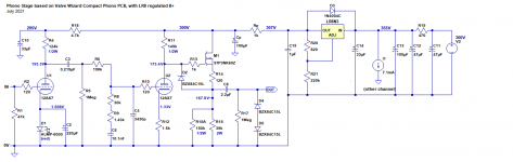
EDITED TO ADD: attached corrected schematic
More to come...
Holy crap!! YOU'RE RIGHT! I do have it shown wrong on the schematic. Fortunately, the parts are in the correct locations in real life, on the PCB. Strangely enough, in simulation the location of those resistors doesn't make a difference to the outcome. Very odd. And...
I think I declared victory prematurely. There seems to be a problem.
I powered down the preamp so I could switch tubes. When I powered it back up, there was hardly any sound. Oops. I shut it off again, let it sit for 10 minutes, came back, powered it up, and took measurements. Both LR8s were outputting only 80VDC. OK, try a different pair of tubes, let it sit, try again. This time I get the expected 315V from the left channel LR8, but only 110V from the right channel LR8. Hmmm...
I've put in a pair of known good 12AX7s and I'm letting the preamp sit for a good long while.
These LR8s are flaky. If I zapped one, it was from simply shutting the preamp off and then powering it back up 3 or 4 minutes later. I may be finding the real reason nobody uses LR8s this way.
EDITED TO ADD: attached corrected schematic
More to come...
Attachments
Last edited:
Yeah the schematic doesn't follow this other popular LR8 Regulator from a ham. I'm following this because in process of making an LR8 PCB now. I was contemplating adding some capacitance to the adj with a protect diode. I hope its just a schematic error and not actually wired already.
View attachment LR8N_TIP50_solid-state_filter_choke_or_field_coil_replacement.pdf
View attachment LR8N_TIP50_solid-state_filter_choke_or_field_coil_replacement.pdf
Yes, I drew up the schematic wrong, but wired it up right. The corrected schematic is attached to post 34.
I found another issue. It seems there's a power supply resonance down low in the 2Hz range, caused by R18 and C10. In simulation I see the bump in response only -4dB from the output with 5mV RMS input signal applied with an inverse RIAA. That looks like trouble.
I can't physically fit a larger part for C10, so I'm not sure what to do about this. I might have to wire in a larger capacitor off-board. Yikes. Down the rabbit hole I go...
But first I have to see if I can get the LR8s to come back to life. If I blew one of them, then I think I'll give up and wire up a Maida, or even put a passive RC in its place.
.... a few minutes later....
And the LR8s are back. It seems they like to protect themselves a lot. I'll have to be careful turning the preamp off and on. Inconvenient, for sure.
Last edited:
Calling all moderators... Can I ask a favor? Can you please remove the schematic from Post 32?
The bad schematic is this one:
The LR8 is wired up wrong in that schematic. I wouldn't want someone to come into this thread cold, download that image, and wire their LR8 incorrectly. I hope that's OK.
--
The bad schematic is this one:
Code:
[url]https://www.diyaudio.com/forums/attachments/tubes-valves/966387d1626035185-riaa-preamp-value-caps-vs-regulated-stabilized-psu-compact-phono_as-built_2021-07_rongon_00-png[/url]The LR8 is wired up wrong in that schematic. I wouldn't want someone to come into this thread cold, download that image, and wire their LR8 incorrectly. I hope that's OK.
--
I think I have a strategy for fixing the inadequate power supply decoupling to the input stage. I can increase the value of R18 from 4.7k way up to 22k, and since the 12AX7 draws so little plate current, the voltage at its plate only decreases by 5V.
This change should reduce the subsonic resonance from only -4dB below 5mV input signal level to -9.5dB below that level. I hope that's enough.
I am dreading taking the audio boards out of the chassis and removing/replacing yet another part. Argh. Next time I'm going to wire up the PCBs outside of the chassis, for the testing phase. My aluminum Bud box is getting pretty well scratched up.
Here's the schematic for the proposed change, with predicted voltages.
--
Attachments
I wonder if the inrush current you get due to Cp and C10 triggers the protection. If so, a capacitor across R21 (with a protection diode to the LR8's input) might help it starting up as well as suppress its noise.
I think I have a strategy for fixing the inadequate power supply decoupling to the input stage. I can increase the value of R18 from 4.7k way up to 22k....--
Radiotron 4th suggests this R be 20%-30% of the plate resistor. Which is indeed 25k-37k, or what you say.
I shudder when I see people put 1k or less to decouple a single 12AX7. What is the point? What is the need?? If this is the first stage in a multi-stage amp, you can't even need a big signal, so high B+ is only marginal benefit.
- Home
- Amplifiers
- Tubes / Valves
- For RIAA preamp: Large value caps vs. Regulated/Stabilized PSU