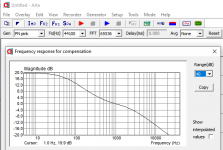
I also have an alternative method for phono frequency response test without hardware anti-Riaa. I load textbook Riaa curve numbers as FR compensation filter in ARTA or alike FFT analysis software. I then run noise from its software generator in a loop from the audio card's output into the phono and back to the audio card's input. The resulting curve includes any deviation of the actual phono curve from a perfect mathematical Riaa model. 😉
How do you load the RIAA curve numbers as FR compensation data?
Set 1kHz at 0dB, then pick a frequency and set it at + or - this or that many dB from 1kHz?
For FFT phono tests you will also need make a shielded resistor divider to cut soundcard output high signal and noise down to useful levels. Say 10k in series 100 Ohm to ground (1:100).
How do you load the RIAA curve numbers as FR compensation data?
Set 1kHz at 0dB, then pick a frequency and set it at + or - this or that many dB from 1kHz?
You prepare a text file like those for microphone compensation when measuring speakers and you load it. In Arta specifically has to end with .mic
Yes, you normalize for 0dB at 1kHz.
For $80 USD the KAB PreConLP Inverse RIAA includes the attenuator, comes in a shielded enclosure, and seems to have all the must-have features. Yes, a little expensive, but I'd only buy it once (and it's not that much more expensive than Hagerman's Inverse RIAA PCB).
KAB GREAT SOUND ESCORT PRECONLP AT KABUSA.COM
Looks OK?
--
KAB GREAT SOUND ESCORT PRECONLP AT KABUSA.COM
Looks OK?
--
Looks very good and you can also run square wave response tests with gen & scope to see about phono ringing with it. Soundcards are lousy with squares.
Cool. Beside, I like Kevin (KAB). I bought a Technics SL1200mk2 from him like 15 years ago, and a few odds and ends over the years. He's located not far away, and he carries a lot of handy stuff for vinyl enthusiasts like me.
I just found out that the freeware audio editor Audacity has a Filter EQ function with an RIAA preset, which you can invert. I suppose I could make a WAV file of white noise with an inverse RIAA EQ applied, then play that into the preamp, record what comes out, and see how far off flat that is.
EDIT TO ADD:
The feature is buried, but it's there. I was able to create a WAV file of 30 seconds of white noise with inverse RIAA curve applied.
Am I correct in thinking that if I play this (attenuated by a lot!) into the phono preamp, the output should be restored flat response white noise?
Attachments

Last edited:
That looks like anti Riaa EQ for the software generator. You should be good without pushing invert I guess. In ARTA its a microphone compensation curve. Like when it measures xdB at 10kHz the curve tells it how much it should be pushed up when displayed because the mic is dull.
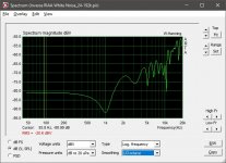
Consider pink noise too if you will notice phono overload symptoms with white. To see pink noise flat it takes enabling the octave smoothing function when played back is the thing to remember.
Consider pink noise too if you will notice phono overload symptoms with white. To see pink noise flat it takes enabling the octave smoothing function when played back is the thing to remember.
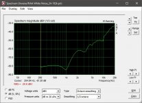
OK, so I ran Arta and did Analysis > Unsmoothed DFT Frequency Response/Spectrum and Single-gated Smoothed Frequency Response/Spectrum, and got what's in these two screenshots.
Not quite what I expected, but it looks kind of/sort of close...?
My thinking is that if you take white noise and play it through an RIAA EQ filter, the highs will be rolled off according to the RIAA characteristic.
If you take white noise and play it through an inverted RIAA EQ filter, the highs will be *boosted* according to the exact *opposite* of the RIAA characteristic.
If I take white noise with inverse RIAA applied and play that into the preamp that applies the RIAA EQ characteristic, if both versions of the RIAA (inverted and normal) are correct, they should sum back to flat response (all frequencies at equal amplitude). If anything is boosted or attenuated at the output of the RIAA preamp then that's the error.
I could record the output of the preamp playing the recorded white noise with inverse RIAA and import that WAV file into Arta, then have it run these frequency response/spectrum analyses.
All this assumes the inverted RIAA filter applied to the white noise is actually accurate. That might not be the case with Audacity's built in effects/filters.
It looks like the computer stuff might be giving too much detail, and showing me its own internal errors. Now I have to think about upgrading my PC sound gear? Will this never end??
--
Attachments
Last edited:
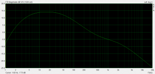
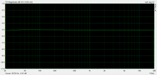
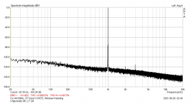
Unfortunately its a mess. Examples from testing a prototype phono of mine on ARTA to know what kind of shapes to look for: A. Phono raw FR (Riaa) B. Phono FR compensated by software Anti-Riaa. C. FFT for Phono at 62dB gain setting and 1V RMS output.OK, so I ran Arta and did Analysis > Unsmoothed DFT Frequency Response/Spectrum and Single-gated Smoothed Frequency Response/Spectrum, and got what's in these two screenshots.
Not quite what I expected, but it looks kind of/sort of close...?--
Attachments
I decided to first try it the old fashioned way, so I bought that inverse-RIAA box from KAB. I have a Tenma audio signal generator and a Rigol oscilloscope. I'll have to finally hook it up and take some measurements.
My friend has the necessary gear along with the Hagerman inverse-RIAA PCB (with the 'Neumann' 50kHz shelf). Even though observing square waves through that wouldn't be useful, I could still see the 20Hz-20kHz response with that.
My friend has the necessary gear along with the Hagerman inverse-RIAA PCB (with the 'Neumann' 50kHz shelf). Even though observing square waves through that wouldn't be useful, I could still see the 20Hz-20kHz response with that.
You did the right thing. Instead of sorting out all the details in testing reliably with software and soundcards when starting from zero you will be better off making five new tube phonos. 🙂
Believe it or not , there are circumstances where you can make an audible difference between two circuits, one passing 10khz square wave , the other passing 20 kh square wave on the same load.My first hybrid phono proved that to me, but the difference wasn't because of the wider range, but because the lowest output impedance circuit driving the riaa network better also happened to output 20khz sqw and driving a reactive circuit with a lower impedance circuit will also allow for wider bandwidth...Even though observing square waves through that wouldn't be useful, I could still see the 20Hz-20kHz response with that.
Solid state folks talk about this in terms of a beyond-worst-case condition of being driven by an imaginary perfect rising or falling straight voltage edge. No actual amplifier can keep up, and the amplifier under test is stressed to a limiting condition of slewing non-linearly between two different output voltages, when driven by a (close enough to) zero time voltage step. The rate of change of output voltage over time in this overload condition is called it's slew rate. (The nautical military origin of the term is interesting.)
This is important in audio circuits, especially RIAA amplifiers, because many optimizations are limited by available charging / discharging currents. There's a magical conversion of volts/time = current/capacitance. Operation with signal even remotely near the limiting condition of slewing is very non-linear, so mind where you step!
All good fortune,
Chris
A lower output impedance driving the (much higher impedance) RIAA network will definitely perform better, or course. A wheezy high impedance driver sourcing a measly half a milliamp might slew into the complex load presented by the EQ network. However...
Low output impedance drive comes from low impedance driving circuits, which cost more money either because of higher plate currents or the added follower/buffer (in the case of tubes)... or are solid-state.
I guess this argument leads to the inevitable conclusion that a 12AX7 by itself just sucks as the first stage in a phono preamp (driving the RIAA EQ network from its plate).
Yes, that's true. But building with 12AX7s is cheap. Very economical power supply because of the low current demand. I have dozens of 12AX7s in the tube caddy, so those are free. Low wattage resistors are cheaper than Mills wirewounds or 3W metal films. It all adds up.
This was a practice run preamp build. I've learned a lot, with thanks to you all.
1) Decouple that first stage effectively!!! As PRR pointed out, the wise man of RDH4 said that the decoupling resistor should be at least 20% of the value of the plate load resistor. So for example, with a 150k plate load R use at least a 33k resistor for the decoupling R.
2) Small errors in the RIAA EQ make an audible difference. I 'felt' the difference by dropping the 10kHz response down by -1dB. After that small change, the preamp sounded a lot better to me.
3) An inverse RIAA network, signal generator, and oscilloscope are absolute necessities. (I'm awaiting delivery of an inverse RIAA from KAB.)
4) LR8s are not worth messing with.
5) A well-done passively filtered/decoupled PSU can perform fine in a tube RIAA preamp BUT... relatively low impedance/high gm triodes (D3a-triode, 6DJ8, etc) will benefit from the lower Zout of a regulated PSU, due to their much lower rp.
6) Grid stopper values can be higher value than you think. There's probably no harm in putting a 1k ohm grid stopper on a 12AX7 or 6DJ8 in the first stage of an RIAA preamp.
7) I really do need at least 44dB of gain to get my LPs to play at about the same perceived volume as my digital sources.
8) With a 12AX7, you can drastically change the tonal quality of a particular MM cartridge by changing the value of the input load resistor (normally 47k). The flip side of this is that a high capacitance input tube is a pain in the keester!
9) Pay the extra money for known-good RCA jacks! I purchased some good-looking RCA jacks from an electronics surplus seller, but the diameter of the jack itself is too narrow, so RCA plugs fit too loosely in them. It's not a huge problem because this preamp has the jacks on top, so the plugs insert straight down into the jacks. But if the jacks were mounted horizontally the plugs would be likely to fall out with the slightest jostling. (I bought some Rean jacks which look very good.)
10) Some people really don't like LED cathode bias in the first stage of an RIAA preamp. Fair enough. I'll have to swap in RC cathode biasing and listen for the difference.
11) A 12AX7 RIAA preamp can sound pretty good! 🙂
Last edited:
You're right about cost.
My RIAA uses 8 tubes, but it sounds excellent. I also built an RIAA with only 2 tubes that was alright but there wasn't enough gain (so I used a step up transformer on the output).
Cost vs performance I'd go with a 4 tube CCDA design, but the 8 tube design moves the "load resistor heat" to the top of the chassis (since there are no plate resistors, just another triode as the load) whereas the 4 tube design makes a few watts of heat in the chassis.
I feel the LR8 would work fine with a pass device, too. I haven't tried mine yet since I got them from China a few years ago and I don't even know if they are real.
I might attempt to have a series regulator with a zener string and a depletion MOSFET, too. it "should" work... I'm thinking 75V x4 for 300V with a 400V input and the MOSFET would waste 100V/50mA as heat.
Last edited:
Yes, absolutely, agreed.
The other cheap thing about a 12AX7 RIAA is that it doesn't make much heat, so it doesn't need a lot of ventilation. I have my 12AX7s hanging upside down, which I'll never do again, but it still doesn't get really hot in there. I might drill some holes in the top to aid in convective cooling. Or maybe stick a couple of computer CPU heatsinks on the top deck so there's at least something to look at! 😀
I think a 4-tube CCDA like Broskie's Tetra Sans is a good compromise between cost and performance.
I was thinking it would be fun to do another 12AX7 RIAA but this time with MOSFET source followers after each triode, and try a lower impedance RIAA network, to see if that makes a big difference in the sound. When used as a source follower, FQPF2N60 has a calculated input C of about 28pF. I think a 12AX7 with Ip = 1mA can drive that without slewing on audio frequencies... I think.
MOSFET source followers are great for something like a 12AX7, because you don't have to worry about heater-cathode voltage getting too high. I think 12AX7 likes a high Vp (it's a high impedance triode, remember), so at least 150V Vp-k is needed. It seems to work well with 200V at the plate, so with a 300V B+, 100k Rp, Ip = 1mA. Very standard. But a DC-coupled cathode follower after that would need its own heater supply, lifted to +130V to +160V. Added cost, complexity. As long as the input C is low enough, a MOSFET works better in every way, and is a lot cheaper to implement.
12AX7 -> MOSFET source follower -> passive EQ -> 12AX7 -> MOSFET source follower.
No CCDA there, though. The MOSFETs will need Ids = 5mA to keep their Cin down.
Next time, maybe.
I do not test phono stages, but I do test the power amplifiers I design.
But the same method will work for phono preamps too.
The Denon Audio Technical Test CD has many signals.
One test signal is the narrowest pulse a RedBook CD player can output (a single sample time).
It is full scale positive DAC amplitude.
It is 1/44.1k = 22.676 usec wide.
But what you see at the CD player output after the digital filter looks like a cosine wave,
(it has pre and post "ringing").
That pre and post ringing caused by the digital filter is the same as the pre and post ringing of the square wave on the same test CD. No surprise here.
It makes the FFT display look like a flat spectrum, all the way to 22.05kHz, and then the amplitude drops precipitously beyond that (Nyquist).
Any un-flat frequency on the FFT is the un-flatness of the amplifier.
So, you should be able to apply a reduced amplitude of that impulse at your phono preamp input, and then see the RIAA playback frequency response curve of your phono preamp.
Last edited:
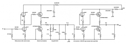
Maybe I'm boring or predictable, but this is my take on making a tube/MOSFET hybrid. The MOSFETs are IXTP08N100D2 - a 1000V 800mA Depletion MOSFET (because I find transistors fragile, I overspec the parts)
TVS gate diodes not shown but you better damned well use them!
If you run the second pair of MOSFETs hard enough, you could drive headphones directly (if you make the 4u7 cap bigger), too!
http://ixapps.ixys.com/DataSheet/DS100182C(IXTY-TA-TP08N100D2).pdf
TVS gate diodes not shown but you better damned well use them!
If you run the second pair of MOSFETs hard enough, you could drive headphones directly (if you make the 4u7 cap bigger), too!
http://ixapps.ixys.com/DataSheet/DS100182C(IXTY-TA-TP08N100D2).pdf
Attachments
Last edited:
- Home
- Amplifiers
- Tubes / Valves
- For RIAA preamp: Large value caps vs. Regulated/Stabilized PSU