"they" said the 50khz filter was something to compenate for an internal resonance of the Neumann cutting head or smth like this...but i have to dig deep into some 100 pages of Neumann VMS schematics to find that evidence...if there's any of it.
Last edited:
26pF seems incredibly low for 1m cable plus arm wiring.
260pF. Sorry about that. It was actually 0.026nF but I converted without the zero.
Did you also press the delta/zero button on the DMM first? So to null residual capacitance in meter and probes as much as possible.
What is Miller Capacitance?
The formula for determining the total input capacitance of a triode stage is as follows:
Cin = Cgk + Cgp*(A+1)
where: Cin = input capacitance
Cgk = grid-to-cathode capacitance, composed of the internal tube capacitance plus the stray capacitance
Cgp = grid-to-plate capacitance, composed of the internal tube capacitance plus the stray capacitance
A = stage gain
__________________________
For a 12AX7, this comes out to at least 150pF and often as high as 200pF, for the triode alone.
I assume the worst, so 12AX7 Cin = 200pF for me.
50pF for the tonearm wiring,
100pF for the tonearm to preamp cable,
200pF 12AX7 Cin
20pF for preamp input wiring
total Cin for a 12AX7 phono preamp is 370pF at minimum
--
Thanks for this.
So for 6N1P, Cgk = 3.2pF, Cgp = 1.6pF A=33 but in my case the stage gain is 1/2 mu so ~ 16
So (3.2 + 1.6)16 =76.8pF? Plus stray capacitance etc? In my case there is only the RCA and one inch of wire for stray capacitance and of course the short PCB traces... Once again, the interconnect is 260pF not 26pF so roughly 400pF || 47k in my set up? I'm using the Pickering XV-15 which is the same as the Stanton 681. Excellent cart.
FWIW, I had a Numark turntable that had 1000pF in parallel with the cart inside the deck. I cut that out and had treble again! My Stanton decks came with interconnects that measure 11nF! They also have a switchable RIAA preamp built in so I figure they expect you'll use it. I use those cables for the record loop on my minidisc and tape now 🙂
Last edited:
Did you also press the delta/zero button on the DMM first? So to null residual capacitance in meter and probes as much as possible.
It read 0 before the measurement... It's probably not very accurate since it read 0.026nF instead of displaying in pF. It gives a rough idea anyway though.
So (3.2 + 1.6)16 =76.8pF?
No, 3.2 pF + 1.6 pF * (33/2 + 1) = 31.2 pF. Only the anode-grid capacitance gets A + 1 times the signal voltage across it, which causes Miller effect.
I think I'll wire up my own inverse RIAA for testing.
Is there a circuit that you all would recommend? There are different circuits shown in...
- the Lipshitz/Jung paper
- Morgan Jones "Valve Amplifiers"
- Merlin Blencowe "Building High Fidelity Tube Preamps"
or it might be worth it to buy the KAB one for $80 USD (KAB Electro Acoustics http://www.kabusa.com) because it's in a nice enclosure, shielded, etc.
??

Did you add 0.7pF to account for stray C for Cgp and Cgk? That's standard practice when working with SPICE models, so is probably a good idea when figuring out Cmiller too.
I'm an uneducated moron when it comes to doing simple algebra.
There's a certain order of operations you have to follow when solving an equation.
"The top priority is your parenthesis, then exponents, followed by multiplication and division, and finally addition and subtraction (PEMDAS)."
***Thank you Marcel for making me look that up!***
So, for our Miller C equation,
Cgk + Cgp * (mu + 1) =
Step 1) Solve what's in the parentheses (mu + 1)
Step 2) then do the multiplication (Cgp * the sum of mu + 1)
Step 3) now do the addition (add Cgk to the result of step 2)
For your half-mu 6N1P:
3.2 pF + 1.6 pF * (33/2 + 1) =
mu = 33, divide that by two to get 16.5
add one and you get 17.5
multiply that times 1.6pF (Cgp)
17.5 * 1.6 = 28pF
add Cgk or 3.2pF
28pF + 3.2pF = 31.2pF
Now I'm going to try that for a 12AX7 with plate load R...
Cgk = 1.6pF (I'm going to add 0.7pF to account for strays, so 2.3pF)
Cgp = 1.7pF (plus 0.7pF to account for strays, so 2.4pF)
mu = 70 (typical, IRL)
Cgk + Cgp * (mu + 1) =
2.3pF + 2.4pF * (70 + 1) = 172.7pF
I usually assume the worst case, so I assume 200pF for a 12AX7 with bypassed cathode.
For a 12AX7 with unbypassed cathode, I figure the gain will be about 40X.
2.3pF + 2.4pF * (40 + 1) = 100.7pF
Again I assume the worst, so let's say 125pF Cin for an unbypassed 12AX7.
--
Ah! Thanks for the info 🙂
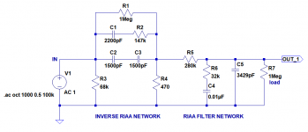
How about this inverse RIAA?
You gave me something to do!
I can test that in good ol' LTspice. Let's see how it does compared to the fancy Laplace transform thing I've been using (which was contributed by one of the members here -- whoever you are... Thank You!).
I'll be back with the results in a bit...
--
How's this look?
1st image is the circuit I used for the test.
1V signal in.
Inverse RIAA network on the left.
RIAA EQ network on the right.
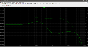
2nd image is the frequency response at the output.
Note the expanded scale!
If I did a valid test, then it looks like this Inverse RIAA network is accurate.
No? Yes?
--
1st image is the circuit I used for the test.
1V signal in.
Inverse RIAA network on the left.
RIAA EQ network on the right.
2nd image is the frequency response at the output.
Note the expanded scale!
If I did a valid test, then it looks like this Inverse RIAA network is accurate.
No? Yes?
--
Attachments
If you want to compare it against the Laplace thing, you could swap its numerator and denominator. A voltage-controlled voltage source with value
Laplace = (318E-6*s+1)/((3180E-6*s+1)*(75E-6*s+1))
would be a perfect RIAA correction. If you connect that to the inverse RIAA network, the only inaccuracies in the transfer of the cascade of these two would come from the inverse RIAA network.
Laplace = (318E-6*s+1)/((3180E-6*s+1)*(75E-6*s+1))
would be a perfect RIAA correction. If you connect that to the inverse RIAA network, the only inaccuracies in the transfer of the cascade of these two would come from the inverse RIAA network.
I'll try turning the Laplace inverse-RIAA upside down and putting it in series with the proposed RC inverse-RIAA at some point.
For now, I spent some time swapping cartridges and trying different load Rs.
- Pleasant surprise! Now, with the attenuated HF response in the RIAA EQ, the AT-VM95E sounds very good. It really is good at separating out individual sounds. Loaded with 15k the highs are mellow, but maybe unexciting. Loaded with 32k it still doesn't sound shrill like it did before the change to the RIAA EQ. This is a fantastic cartridge for $60 USD, even into a 12AX7.
- Denon DL110, which was so much superior in sound to the others before, has fallen back into the pack. It still sounds good, very clear. The bass is looser and boomier than the AT, for sure. The highs are sweeter, cymbals sound fantastic, but any fuzz and distortion in the recording seems accentuated. It could be tracking error, though. I have it lined up, but I haven't done the whole neurotic-obsessive tweaking the cartridge ritual yet.
- Shure M35X/Jico elliptical - This sounds really good with either a 36k, 40k or 47k load. The heavier loading softens the high frequencies. A ton gôut, I suppose. The Shure has a tendency to get muddy with complex passages. It doesn't separate out the individual instruments as well as the AT-VM95 or DL110. Generally a little murky, or slightly muddy. Pleasant, though.
Now the preamp is much more forgiving of different cartridges. I think that's a good sign.
This has been quite an adventure. Vacuum tube RIAA preamps really are challenging. And to think this is about the simplest version there can be, basically just the RCA Tube Manual example design with some updates.
Last edited:
FYI Fwiw I happen to recall my 1m Cardas tone arm wire (an option with the Kuzma arm) measures about 47pF pos/neg per side from cart to Rca. It has no junctions from cart clips to Rcas.Maybe it's impossible to make a 1m tonearm-RCA cable that has less than about 75pF capacitance.
--
It has no junctions from cart clips to Rcas.
That is why you can get such low capacitance.
I'm too clumsy to rewire my own tonearm, and I'm too poor to pay for someone else to do it.
My solution will be to get a 0.6m 'shortie' cable, which should measure about 60pF.
Or I'll build another preamp. I'm thinking cascode input stage for the next one.
--
In going back over my notes, I realize I may have confused 3340pF with 3430pF. (D'OH!!)
The theoretical exact value for the shunt capacitor is 3429pF. I had gambled that the 2nd stage 12AX7 would have about 100pF of input C. Add that to the 3340pF (measured) and I should get 3430pF.
It may be that the Cin of the 2nd stage isn't quite as high as 100pF. Maybe it's 75pF? At any rate, adding 470pF brought a big improvement in tone quality, with all cartridges. I'll be astounded if that turns out to be 'wrong' and the response is down by more than -1dB at 10kHz.
I need to get an inverse RIAA together...
I also have an alternative method for phono frequency response test without hardware anti-Riaa. I load textbook Riaa curve numbers as FR compensation filter in ARTA or alike FFT analysis software. I then run noise from its software generator in a loop from the audio card's output into the phono and back to the audio card's input. The resulting curve includes any deviation of the actual phono curve from a perfect mathematical Riaa model. 😉
- Home
- Amplifiers
- Tubes / Valves
- For RIAA preamp: Large value caps vs. Regulated/Stabilized PSU