did the tone change after switching to 12at7?
It's the lack of mids you're experiencing ...now you've left with more of a tipical Fletcher Munson curve that wes lately dimissed by Harman curves iterated for a few times especially when applied to headphones.Do you listen on headphones or speakers?
Equal-loudness contour - Wikipedia
What Is Harman Curve? - HeadphonesAddict
Last edited:
Tone changed very slightly w 12at7 instead of 12ax7. However, after R9 changed to 590R, 12ax7 sounds great in there. I may have had a mid boost originally.
Listening thru loudspeakers jbl lsr305 nearfield.
I just received an inverse Riaa today, so we'll see about FR in testing.
3. Harman research for in home listening shows preference for evenly gradually falling hf response in room at the listening position. A slight dip centered around 1khz might be pleasant, but only if very shallow dip. Otherwise would sound hollow and weird
I just received a 2 ft (roughly 0.6m) DIN-5 to 2x RCA-M tonearm-to-preamp cable. (There has to be a better name for that type of cable!)
I had it made by Blue Jeans Cable. It cost a little more than $40 USD, which I think is quite reasonable. It's nicely made, looks good, feels good, has high quality plugs on it.
My 1m (3.3 foot) Sonic Frontiers by Cardas cable measures about 130pF.
This new Blue Jeans Cable measures about 80pF.
It seems the best you can do for a DIN5 phono cable is roughly 40pF/foot (130pF/m).
The tonearm wiring adds about 30pF, so the Blue Jeans Cable measures 110pF once connected.
I figure the Cin of the 12AX7 input stage is 150pF to 200pF.
I'm just over the upper limit of the recommended Cin of 250pF for present-day moving magnet carts like Audio Technica, Nagaoka, Ortofon (and Shure too, even though they're out of production now). Somewhere from 260pF to 310pF.
I'll have to do some listening and try to find out if there is a noticeable difference.
The KAB inverse RIAA network box came too. I have to get the signal generator, 'scope and that hooked up and sorted out, so I can see if the response from the preamp's RIAA EQ network is close to what LTspice predicts. That will be a good test...
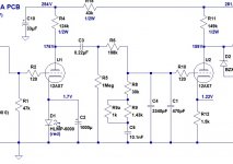
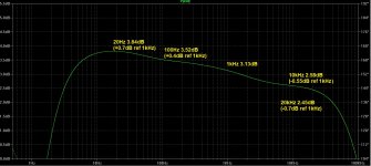
I've attached a schematic and LTspice predicted freq resp of the current 'state of the EQ' in this preamp.
--
I had it made by Blue Jeans Cable. It cost a little more than $40 USD, which I think is quite reasonable. It's nicely made, looks good, feels good, has high quality plugs on it.
My 1m (3.3 foot) Sonic Frontiers by Cardas cable measures about 130pF.
This new Blue Jeans Cable measures about 80pF.
It seems the best you can do for a DIN5 phono cable is roughly 40pF/foot (130pF/m).
The tonearm wiring adds about 30pF, so the Blue Jeans Cable measures 110pF once connected.
I figure the Cin of the 12AX7 input stage is 150pF to 200pF.
I'm just over the upper limit of the recommended Cin of 250pF for present-day moving magnet carts like Audio Technica, Nagaoka, Ortofon (and Shure too, even though they're out of production now). Somewhere from 260pF to 310pF.
I'll have to do some listening and try to find out if there is a noticeable difference.
The KAB inverse RIAA network box came too. I have to get the signal generator, 'scope and that hooked up and sorted out, so I can see if the response from the preamp's RIAA EQ network is close to what LTspice predicts. That will be a good test...
I've attached a schematic and LTspice predicted freq resp of the current 'state of the EQ' in this preamp.
--
Attachments
Last edited:
Just wanted to wrap this thread up with the findings from using the KAB inverse RIAA with signal generator and 'scope.
Basically, the real-life output frequency response looks very close to flat, with a slight boost in response in the 100Hz area, and a slight rolloff above 10kHz (looks like as much as -1dB at 20kHz using 12AX7).
Changing the value of C1 (parallel cap from U2 grid to ground) caused very slight changes in high frequency response. Barely observable on the 'scope. Probably difference of -0.5dB and -1dB at 20kHz.
I played with changing the value of C1, deciding by ear alone which I preferred. I found that in this particular preamp, I liked the sound using a 220pF for C1. 470pF sounded too dark. 100pF sounded too bright. The differences were just noticeable on the 'scope (angle of rolloff of HF above 10kHz).
My conclusions:
- LTspice predictions were close to reality. The RIAA EQ came out nearly as predicted, although with ever-so-slightly lower HF response than the simulation predicted. I figure there must be stray capacitances at work in real life that are not accounted for in simulation.
- I prefer a slightly dark sounding presentation. I don't like it when things get too bright.
- Once I got the HF response from the EQ where I wanted it, I enjoyed the sound of the 12AX7 about as much as from 12AT7. They're different, but I couldn't say one is better than the other.
- Listening tests were done using a cheap AT-VM95E cartridge into the preamp. I've since upgraded the stylus to the "ML" version, which made a noticeable improvement in smoothness of the treble frequencies, so the results of my 12AX7 vs. 12AT7 bake-off would probably be different were I to repeat them today.

Hello.
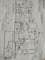
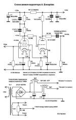
I tried to build a 6f12p phono preamp with a regulated psu.
I plug it to my amplifier:HUM !

I tried to build a 6f12p phono preamp with a regulated psu.
I plug it to my amplifier:HUM !

Question ⁉️
Pourquoi ça bourdonne comme ça ?
tous les fils sont torsadés.
Les filaments sont alimentés par une alimentation régulée et sont mis à la terre.
regards
Pourquoi ça bourdonne comme ça ?
tous les fils sont torsadés.
Les filaments sont alimentés par une alimentation régulée et sont mis à la terre.
regards
I tried to build a 6f12p phono preamp with a regulated psu.
I plug it to my amplifier:HUM !
Not too surprising. Low level, high gain circuits are too critical for this sort of breadboarding.
You could try it with a lab supply to see if the regulator is a big part of the problem.
But rather than waste a lot of time trying to fix this, just build it in a more proper fashion.
I even tried to mount an ez4 rectifier instead two diode, for decrease noise ,i lose around 20v.
Should i build first my chassis for power supplyNot too surprising. Low level, high gain circuits are too critical for this sort of breadboarding.
"Should i build first my chassis for power supply"
The audio circuit will be the most difficult to lay out, so I would do that first.
You could lay out one mono channel, and just duplicate that for the other channel.
In the mean time, you could do more testing with what you have.
I would try a HV lab supply first, if you have one, to see if the hum is affected.
Otherwise, first verify that your regulated PS circuit is in regulation.
Then if the regulated supply is working ok, determine where the hum originates.
Start at the last audio stage, and ground its grid to see if the hum goes away.
Then work backwards one stage at a time, towards the input stage, doing the same for each stage.
Usually phono stages will benefit from DC filaments.
That's a clever screen supply, but you don't want to couple subsonics back to the first stage, so C5 must be very large.
I suspect that 1000uF would not be too large, given that R8 is also shunted by 1/gm of the follower, plus the
screen impedance of the first stage.
That's a clever screen supply, but you don't want to couple subsonics back to the first stage, so C5 must be very large.
I suspect that 1000uF would not be too large, given that R8 is also shunted by 1/gm of the follower, plus the
screen impedance of the first stage.
Descartes wrotes :divide the difficulty to solve the problem.
Generally the screen is normally bypassed to the cathode, not to ground.
We can't let you off that easily.Just wanted to wrap this thread up with the findings from using the KAB inverse RIAA with signal generator and 'scope.
Basically, the real-life output frequency response looks very close to flat, with a slight boost in response in the 100Hz area, and a slight rolloff above 10kHz (looks like as much as -1dB at 20kHz using 12AX7).
Changing the value of C1 (parallel cap from U2 grid to ground) caused very slight changes in high frequency response. Barely observable on the 'scope. Probably difference of -0.5dB and -1dB at 20kHz.
I played with changing the value of C1, deciding by ear alone which I preferred. I found that in this particular preamp, I liked the sound using a 220pF for C1. 470pF sounded too dark. 100pF sounded too bright. The differences were just noticeable on the 'scope (angle of rolloff of HF above 10kHz).
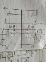
...but for the purposes of analysis I played around with the passive RIAA network values and offer the following suggestions (see picture below).
The issue with high resistance values in passive tube RIAA networks is noise.
Attachments

In my experience, an AC filament supply works fine in an MM amplifier when you use an EF86 in the first stage, decouple its cathode to ground with a big capacitor and use twisted and shielded wire for the filament connections.
Edit: apparently I'm repeating myself, see post #12, https://www.diyaudio.com/community/...-regulated-stabilized-psu.374452/post-6716476
Edit: apparently I'm repeating myself, see post #12, https://www.diyaudio.com/community/...-regulated-stabilized-psu.374452/post-6716476
Last edited:
We can't let you off that easily.
...but for the purposes of analysis I played around with the passive RIAA network values and offer the following suggestions (see picture below).
The issue with high resistance values in passive tube RIAA networks is noise.
You are 100% correct. I stuck with the 10.1nF caps I had for C6 and worked around that. The result was close enough for me (and for my brother, who now has that preamp). Your tweaks certainly make it more accurate. Thanks!
When you're working with 12AX7 or 12AT7 tubes on a pre-designed PCB with no follower after the first stage, you're stuck in a high impedance world. Using lower resistances would load down a 12AX7 common cathode stage. Everything is a compromise.
Last edited:
Marco audio
Ask the mods to move your thread to the Analogue Source
I'm sure you'll have more responses to your enquiry.
Ask the mods to move your thread to the Analogue Source
I'm sure you'll have more responses to your enquiry.
- Home
- Amplifiers
- Tubes / Valves
- For RIAA preamp: Large value caps vs. Regulated/Stabilized PSU