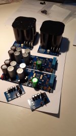
So I got the boards assembled last night! Everything went well, some of the resistore had to be mounted vertically due to space issues.
The one thing that was a bit of a challenge was the transistors....
I have been soldering for 30 years or so and I still had to really concentrate and pull out all of my bag of tricks to get them all soldered on!
The one thing missing is the cap that comes after the solar cells... What value and voltage should that be?
Now I am just waiting on the Leds, Solar cells, and the power trafos. I am thinking about Toroidy as I have had good experiences with them in the past.
Thanks again Jeremy for the great design!!😀
Attachments
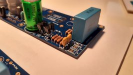

Because there are no through holes on the PCB for the transistors, there are only flat pads. Plated through holes would have made it a lot easier, for some reason this design just has three flat soldering Pads....
That's really weird. 😕
If it’s a single-layer board, I’d drill holes in it for those little transistors.
If it’s a single-layer board, I’d drill holes in it for those little transistors.
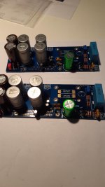
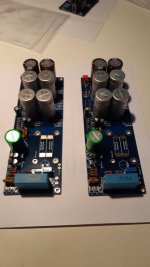
So I got the boards assembled last night! Everything went well, some of the resistore had to be mounted vertically due to space issues.
The one thing that was a bit of a challenge was the transistors....
I have been soldering for 30 years or so and I still had to really concentrate and pull out all of my bag of tricks to get them all soldered on!
The one thing missing is the cap that comes after the solar cells... What value and voltage should that be?
Now I am just waiting on the Leds, Solar cells, and the power trafos. I am thinking about Toroidy as I have had good experiences with them in the past.
Thanks again Jeremy for the great design!!😀
680-1000uf 16vmin, same size as feedback will fit.
Glad you were able to solder transistors. This wasn’t intended for a beginner project. The way I do it is to carefully trim the leads first, pool a little solder on the back leg pad, and try to tin the back leg real quick. Then hold the transistor where you want it and heat the pad, the leg will sit down in the pool onto the pad. You can just just solder the other joints like anything else. It doesn’t feel out perfect but is repeatable.
So I have found a killer deal on some toroidal trafos that are overstock. They are 300va but they have 30v secondaries.
Would 30v. secondaries be to far out of line for the voltages on the boards or would they still be usable?
Thanks guys!
Would 30v. secondaries be to far out of line for the voltages on the boards or would they still be usable?
Thanks guys!
It would mean the capacitors that were in the BOM would be insufficient for handling the voltage on them. But yes you could run that high as long as you have adequate heatsinks.
I'm slowly ploughing thru the threads about this amp, the basic power supply and the Fo-Felix line filter and kept on coming across the reference to this "Antipole Power Supply" and wondered what it was?
Then, on Audio Circle, it seems to be part of the design of the 7297 chip amp's supply - it appears to be a cap multiplier p/s filter but I don't see any mention of it - doesn't it work here?
Then, on Audio Circle, it seems to be part of the design of the 7297 chip amp's supply - it appears to be a cap multiplier p/s filter but I don't see any mention of it - doesn't it work here?
Has anyone done monoblocks for these? Bought everything except for the enclosure and I'm debating, I'm good with a bit more on the budget.
Chassis Size
I know there has been several questions regarding chassis/heatsink size bur I have to ask 1 more
Would this work for Mono blocs ?
2515full Aluminum Preamplifier enclosure/amplifier chassis AMP BOX with heatsink | eBay
These are the measurements:
Product Details:
External dimensions: width 253mm height 150mm depth 311mm
Internal dimensions: width 198mm height 142mm depth 300mm
Package weight:about 5kg/set
Last edited:
I just bought the same thing for mine about 2 days ago and had asked jeremy if it would work and he said it made sense to him. I also did a little mock up that seemed to show it working.
The heatsink is sufficient. It's all about just arranging the parts in it, which you can calculate fairly easily. A transformer might even be able to be vertically mounted in that since it's so tall. That really opens up room for a lot of space.
An externally hosted image should be here but it was not working when we last tested it.
What goes in this spot? 1kohm resistor, correct?
also does anyone have a link to the standoffs for the amp board (the ones on the mounting bom seem too high to attach chips to heatsink), I could probably figure it out but don't want to get it wrong and it would be good if this is my last mouser order for the project.
Also to double check, all of the for the default dualpole bom, all of the parts work for the Antek AS-2225 transformer, right?
Okay, the image isn't showing up, its the spot by the input cap with the two square surface pads (as well as through hole) that is unmarked. Probably a resistor.
You're talking about the solder bridge. There is no component, but you can use a piece of wire/lead.
The Antek 2225 works with the parts.
I don't understand the other question because the chips don't stand off the heatsink.
The Antek 2225 works with the parts.
I don't understand the other question because the chips don't stand off the heatsink.
Imgur: gallery link
Just got one channel mounted and wired. Just wondering if anyone can look at my gallery and let me know if anything looks off, first build so if something looks amiss let me know as it probably is. A couple pictures show I have the wire for the power ground and - reversed on the amp board, it is now fixed w pg going on the furthest left post (it is fixed in a few of the pics).
I reversed the polarity of the voltage regulator on the light board and caught myself pretty quick. Had to apply quite a bit of heat as I was struggling to desolder, is that component likely to fail with excessive heat?
I'll hold for response before powering it up.
- Home
- Group Buys
- Folsom EC7293: PVI Powered Frontend, 60/120w 8/4ohm