I would like to get my hands on a pair of these amps! How can I get added to the list?
send PM to Destroyer OS
I was also considering building 7297 from my old 5.1 amp's wreckage, it got a nice heatsink and a back panel pretty suitable for the build.
SMPS - doesn't it really ruins the sound much?..
I was looking at this one: WX-DC2416 - will it fit?
I used that PS on my first Folsom 7297 build. It is a good option for a budget build. I didn't find it degraded the sound much if at all. The Antipole PS is better, but adds significant cost. Give the SMPS a try, if you like the amp, you can always upgrade the PS later. I did replace some of the caps on the SMPS with better quality ones.
See reply #294: Folsom's great little 7297 Chip Amp
Attachments
Not yet but a new GB is coming up very shortly. PM me your email to get notified.
Awesome, thanks! Please, take my money!
 🙂
🙂Second Group Buy arrived and it's thread is here:
GB#2: Folsom EC7293: PVI Powered Frontend Amplifier, 60/120w 8/4ohm, 0.0005% THD
GB#2: Folsom EC7293: PVI Powered Frontend Amplifier, 60/120w 8/4ohm, 0.0005% THD
help with transistors
hey there,
Populating the amp boards and noted the holes for the transistors were not "through" holes. Assuming this is correct and the transistors are "seated" in the spots with solder (vs. a mistake in the boards). Are folks trimming the leads to minimize the chance of shorts, etc.? Sorry for the noob questions.
Thanks!
Jeff
Trim to any height you're comfortable. Shorter is technically better but don't make it too difficult.
And, no, not a mistake.
And, no, not a mistake.
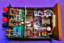
Getting close to finishing. Both PS rails are at ~70v. The photo voltaic voltage is a little under 8v. No continuity between the chips and the heat sinks. I have a question about PS grounding.
Is it acceptable t float the PS ground or should I attach or the star ground vis a cl-60 (the green loose wire attaches to the ground of the PS). I did something similar with a Pass F-6. Not sure if applicable here.
Thanks!!!
Jeff
Is it acceptable t float the PS ground or should I attach or the star ground vis a cl-60 (the green loose wire attaches to the ground of the PS). I did something similar with a Pass F-6. Not sure if applicable here.
Thanks!!!
Jeff
I made some stupid mistakes and trashed my amp. Now to repair....
One (yes, one) of my errors was omitting the diode on both sides. After adding the diode, I get ~.5 volts at the binding posts (on one side). The offset adjust barely changes things at all. Did not hookup speakers, etc. Ran the amp at full voltage for just a bit w/o the diode. Per Jeremy's directions supposed to be <.5mv Am guessing i smoked this side of the amp (even though no "smoke" appeared). Can someone please provide some guidance. Sadly, it gets worse...
On the other channel I had 2 errors- No diode and i carelessly screwed the polarity on the power from the PS. Smoked the center cap on the light board before figuring out my error. Replaced the cap and then smoked the amplifier chips at ~70v (variac). I have removed the amp chips and the transistors and will replace those. perhaps that is what i need to do on both boards?
Nothing other than the amp chips (resistors or caps) appears damaged on the worse board. Do you recommend changing anything other than chips and transistors prior to trying again? i could get new boards and start fresh. hate to replace the hard to get caps. hopefully, no other stupid mistakes are lurking. Move slowly, be careful (advice to myself).
Jeff
Always feel free to email pictures before turn on, to be reviewed by us.
PM sent on your amp Jeff.
PM sent on your amp Jeff.
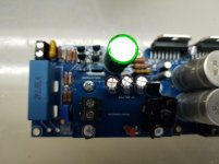
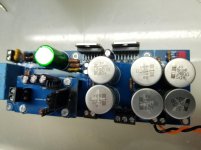
This is the board that I omitted the diode (next to the 3 resistors) AND screwed up the polarity at the input. I blew the center cap on the light board before figuring out my bonehead move. It was after replacing the blown cap that I smoked the amps (assuming because of the omitted diode).
Anyway. I replaced the 3 caps and the regulator on the LED board. I replaced all the caps on the main board except the large, green cap; the small, red cap (1nf?) and the silver, pricey ones. I replaced the transistors and the amp chips. i installed the diode next to the 3 resistors. i did not replace the offset pot or any resistors.
Planning to try again with the variac tomorrow. Will double check cap orientation, diode orientation, wiring polarity and isolation of the chips. Sure hope to not see any smoke.
Was thinking it would be prudent to desolder the amp bridge and check the light voltage before proceeding.
Any other things i should do before trying again? Thanks for any help!
Attachments
![20200911_164045[7629].jpg](/community/data/attachments/799/799855-181e4c10f6977a547375df02799e210c.jpg?hash=GB5MEPaXel)
Yes, they are sitting nicely flush.
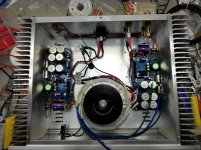
Installed the new board (right). Checked everything over a few times and nervously turned the variac up. No smoke, sparks or fire. Very happy for that. Let it cook for a few minutes. measured offset and got it adjusted to .0001 volt.
The other channel (left) still measures 0.3v. The regulator on the light board is measuring much hotter than the right channel ( 145 vs 95 degrees F). the caps appear to be a bit warmer as well. Was thinking or ordering a new regulator for the left LED board and replacing the caps. I will order new amp chips as well. I already have the transistors. I'll change the Clarity cap to the Rifa as well.
Thanks for the help! Any thoughts or advice is welcome.
Jeff
Attachments

You should be able to read 24v across the big red resistors on PVI board, can you check?
If that's too hard to measure the voltage across the LED board pins behind the regulator should be 24v below the input voltage to the PVI board.
If that's too hard to measure the voltage across the LED board pins behind the regulator should be 24v below the input voltage to the PVI board.
Last edited:
- Home
- Group Buys
- Folsom EC7293: PVI Powered Frontend, 60/120w 8/4ohm