Nelson,
I doubt I put it that way, however, appropriate harmonic spectrum is a condition of transparent sound, but there are other considerations of importance too. Although this is a well-behaved topology, I would not have chosen it for a headphone amp in the first place. You can make refinements ad infinitum, but you cannot eliminate its inherent shortcomings.maybe it's just like Lumba Ogir says, it's all about harmonics
Lumba Ogir said:... but you cannot eliminate its inherent shortcomings.
Which are?
I tried some other tweaks to the amp with CM. First CFP with SK170/BC559 with no improvement. Then I tried cascoding the input stage with SK246 and now the sound is smoother and less piercing. Still leaner/brighter and than the amp without CM.
Lumba, you know I don't have any deeper knowledge. I'd be happy if you showed me an example. Do you think I could still use the front end and tweak the output to single end? Just to find out what it does to the sound.Lumba Ogir said:roender and Nelson,
I would change the push-pull output stage to single-ended.
nelsonvandal said:I'd be happy if you showed me an example.
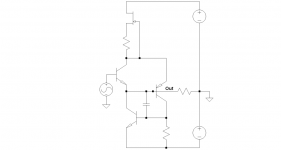
SE buffer by Steven (the best SE buffer known to a mankind this side of universe, if you ask me)
Attachments
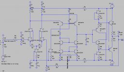
Can you please add some values to this circuit. I can't get it to simulate any good.aparatusonitus said:
SE buffer by Steven (the best SE buffer known to a mankind this side of universe, if you ask me)
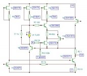
A bit too complex to start with, but maybe this is what I eventually end up with.Lumba Ogir said:Nelson,
would this work? Should be pretty linear...
I tried some tweaks again. I cascoded the input stage à la Borbely. It adds some flavor to the sound, that's for sure. It's brighter than neutral now, and a brighter sound is at first glance always perceived as being more detailed.
I added a Zener between the T3 and T5 collectors to get an even voltage across the folded cascodes. I can't hear any difference, it doesn't simulate any different and it looks the same in RMAA.
I removed the lag comp cap and added source resistors. I'm not sure I can hear any difference with the exception of more noise when listening through IEMs, but I like the idea of dropping this cap after Jonathans reply http://www.diyaudio.com/forums/showthread.php?postid=1739818#post1739818. I still get an almost perfect pulse response without it (in sim).
Attachments
Configure J-fet CCS (use BF244B/C or similar and resistor below) for ~10-15 mA, resistor at the bottom is ~100R, but you will see one Vbe offset (~650mV) at VAS output (current mirror output) 'cos buffer output is at 0VDC. Also, use something like 100pF or more for compensation.
For "Borbely" cascades don't use 2SK170, use low input capacitance J-fet like BF244/5, 2SK246 with higher Vgs, you have to give poor 2SK170 some voltage to work with.
For "Borbely" cascades don't use 2SK170, use low input capacitance J-fet like BF244/5, 2SK246 with higher Vgs, you have to give poor 2SK170 some voltage to work with.
Thank you, I'm going to play with this.aparatusonitus said:Configure J-fet CCS (use BF244B/C or similar and resistor below) for ~10-15 mA, resistor at the bottom is ~100R, but you will see one Vbe offset (~650mV) at VAS output (current mirror output) 'cos buffer output is at 0VDC. Also, use something like 100pF or more for compensation.
For "Borbely" cascades don't use 2SK170, use low input capacitance J-fet like BF244/5, 2SK246 with higher Vgs, you have to give poor 2SK170 some voltage to work with. [/B]
Oops!, sorry, I do use SK246 in the real circuit, I just forgot to change it in the schematic above and now I cant edit that post.
Also, try to take out LTP source resistors R1/R2 if your input pair are matched and thermally coupled.
They're matched to less than 0.5 % IDSS and are close together but not glued. If I remove them I have to use a lag comp cap. Is it better to have this cap than the source resistors?aparatusonitus said:Also, try to take out LTP source resistors R1/R2 if your input pair are matched and thermally coupled.
Nelson, at which Vds are the 2sk170's working when cascoded with 2sk246 in the real circuit?
Personally, I found the sound better with bjt's as cascoding devices, but that seems to be only me. It is more complicated as well.
Rüdiger
Personally, I found the sound better with bjt's as cascoding devices, but that seems to be only me. It is more complicated as well.
Rüdiger
1.8V, if you mean voltage between drain and source.Onvinyl said:Nelson, at which Vds are the 2sk170's working when cascoded with 2sk246 in the real circuit?
Personally, I found the sound better with bjt's as cascoding devices, but that seems to be only me. It is more complicated as well.
Rüdiger [/B]
Me too, but the reason I use SK246 is the lack of space in my little amp. Also, I've been looking at Erno Borbelys desings, and I thought what's good for him is good for me.
I've also tried a CFP input stage with SK170/SA970, but it seemed unstable, and the sound wasn't what I was hoping for.
Rüdiger,
You are not the only one. You once started a thread about that issue, now go back to check my answer.Personally, I found the sound better with bjt's as cascoding devices, but that seems to be only me.
Lumba Ogir said:now go back to check my answer.
Lumba, answers like this are perceived being arrogant at this end of the line.
Rüdiger
aparatusonitus,
I see some problems, but no advantages with Steven`s circuit. Also, it requires a strongly deteriorating compensation capacitor, which I cannot voluntarily accept.
I see some problems, but no advantages with Steven`s circuit. Also, it requires a strongly deteriorating compensation capacitor, which I cannot voluntarily accept.
Could you explain why, please?Also, try to take out LTP source resistors R1/R2 if your input pair are matched and thermally coupled.
Nelson,
very nice, but I would remove D3, it`s not needed for anything (extremely nonlinear and noisy) and lower the value of R8 below 100kOhm.
very nice, but I would remove D3, it`s not needed for anything (extremely nonlinear and noisy) and lower the value of R8 below 100kOhm.
Lumba Ogir said:
I see some problems, but no advantages with Steven`s circuit. Also, it requires a strongly deteriorating compensation capacitor, which I cannot voluntarily accept.
See http://www.diyaudio.com/forums/showthread.php?postid=775787#post775787
Regarding compensating capacitor, there isn't any in Steven circuit, so I've just put one to establish safe operation without oscillation.
Lumba Ogir said:Could you explain why, please?
I believe that without them this circuit will have lower H2 (lower THD as well), something you don't expect with balancing resistors and local feedback. I don't understand the mechanism or theory behind, but it seems to happened (again, I could be wrong here). Added noise is another issue, but not so important here.
- Status
- Not open for further replies.
- Home
- Amplifiers
- Headphone Systems
- Folded cascode headphone amp