I got the Sanyo transistors today. Many thanks to Sigurd Ruschkow. The amp sounds perfect now (well at least I think so). It's almost impossible to hear the difference if I add this amp to the signal path now, 98 % transparent. Slightly dark, but where it fails is depth of image/soundstage. My JLH like amp is more focused, a little more forward, with a pin point accuracy placing the instruments in space. If you've heard AD8620 you know what I mean. But these amps are grainier and maybe this "fantastic" soundstaging is a coloration.
It's weird how sensitive this amp is when it comes to cascode transistors. I'm glad you helped me to find the perfect match.
It seems that the Sanyo transistors are as detailed and energetic as the Toshiba's but without the exaggerated treble, as neutral as the BC's but with more energy and details, just perfect (at least in this amp).
Now I've changed the Philips BC549/559 in the diamond buffer to SA1016/SC2362. The vaguenes and lack of energy has gone. The instruments are better separated and details are clearer. This is without added sibilance or grain. Voices are more focused in the center. Simply better in every aspect. Compared to JLH it's still more laid back, not as forward sounding.
Do you think the transistors in the current mirrors affect the sound?
I think I'll change the tombstoned through hole resistors to 0805 SMD (ELFA stocks KOA) - or should I buy some boutique through hole resistors?
Do you think the transistors in the current mirrors affect the sound?
I think I'll change the tombstoned through hole resistors to 0805 SMD (ELFA stocks KOA) - or should I buy some boutique through hole resistors?
Good progress!
If you have some more of those 1016/2362 try them in the current sources, too.
I would never use those SMD resistors. At the level you are now, I think that you need some better resistors like my favorites TX2352, or why not try the red PRP resistors that PartsConnexion sells (Ayre also uses the red PRP:s).
BTW,
do you have a capacitor in series with the input?
If so, what type?
Sigurd
nelsonvandal said:Now I've changed the Philips BC549/559 in the diamond buffer to SA1016/SC2362. The vaguenes and lack of energy has gone. The instruments are better separated and details are clearer. This is without added sibilance or grain. Voices are more focused in the center. Simply better in every aspect. Compared to JLH it's still more laid back, not as forward sounding.
Do you think the transistors in the current mirrors affect the sound?
I think I'll change the tombstoned through hole resistors to 0805 SMD (ELFA stocks KOA) - or should I buy some boutique through hole resistors?
I never thought I'd come to a point where the sound of resistors had to be dealt withSigurd Ruschkow said:Good progress!
If you have some more of those 1016/2362 try them in the current sources, too.
I would never use those SMD resistors. At the level you are now, I think that you need some better resistors like my favorites TX2352, or why not try the red PRP resistors that PartsConnexion sells (Ayre also uses the red PRP:s).
BTW,
do you have a capacitor in series with the input?
If so, what type?
Sigurd
 . But I guess there's no stopping now.
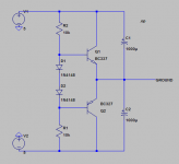
I use no input cap in this amp, but I use a 0.33 uF WIMA MKP from base to base in the output stage and a 10 pF Kemet ceramic NPO in parallel with the feedback resistor. Sanyo WX 1000uF are used as rails to ground capacitors.
In my "JLH", I use WIMA MKP 1uF as input caps, and I'm surprised how little impact they make on the sound.
Everything matters at the top sonical levels. Layout, PCB, components, cables, wires, grounding, mechanical issues, connectors, power supply quality.....etc etc.
If you must have SMD resistors, try the VSMP or VSM from Vishay/texas Components.
I think you have a pot on the input JFETs, right? You need a very good one there, IMO. I use Bulk Metal Foil types.
I would try another feedback cap. Polystyrene is my preferred choice for feedback caps - if needed.
Do you need that 0.33uF cap? If you really do, I would try some other cap like a 33n FKP2 (available from ELFA) or even polystyrene.
Maybe some 0,5mm silver wire for internal wiring? You can get that from Svalander Audio.
Sigurd
nelsonvandal said:
I never thought I'd come to a point where the sound of resistors had to be dealt with
I use no input cap in this amp, but I use a 0.33 uF WIMA MKP from base to base in the output stage and a 10 pF Kemet ceramic NPO in parallel with the feedback resistor. Sanyo WX 1000uF are used as rails to ground capacitors.
In my "JLH", I use WIMA MKP 1uF as input caps, and I'm surprised how little impact they make on the sound.
Yesterday, I compared this to chipamps. I haven't used any of those in a long time. And damn, the amp was only on par with Mini3 (AD8397/OPA690) and bettered by a LISAIII clone with buffered AD797 as L/R and AD829 as ground channel. LISA has a very 3D sound that the discrete amp is lacking.
So I ripped out the discrete rail splitter and stuffed in a TLE2426 as virtual ground and a monolithic opamp as active ground, and that spark of 3D magic has come to this amp as well. Even though I've only used "second grade" chips - LM6171, LM6642 and NE5534 the amp is much better. I think the board is too messy to add the active discrete ground channel again, so I think I have to build a new amp.
I know most of you are non-believers, but the truth is out there. Active ground channel is better than (standard low ESR capacistors) sinking the return currents from the headphones.
Nelson,
I followed your thread with great interest, but in your last post, you lost me. What is a 'discrete rail splitter'? What exactly have you done now?
Rüdiger
I followed your thread with great interest, but in your last post, you lost me. What is a 'discrete rail splitter'? What exactly have you done now?
Rüdiger
I think he probably had a voltage divider with caps
across a single ended power supply and you derive
a new ground from the center of the voltage dividing
network. Awaiting his response of how he did his.
(I sometimes enter a response so I can follow the
interesting threads without waiting for email notifications
of new responses. - I can just search my own entries to
find these threads more easily later on.)
Onvinyl said:Nelson,
I followed your thread with great interest, but in your last post, you lost me. What is a 'discrete rail splitter'? What exactly have you done now?
Rüdiger
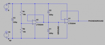
Virtual ground has to be created in some way. This is was my discrete railsplitter. If transistors are matched, it splits almost exactly between the rails. It's simpler and smaller using a TLE2426 as rail splitter or "ground generator" as TI call it.
Attachments
I do not know how much current output from LTC6244.
Have no idea what type of chip amp it is.
But if you think you need more output current
then just add one Single NPN Transistor+pull-down Resistor
or Complementary push pull follower stage
to buffer the op-amp output.
Need not to use one diamond buffer output. But you can.
--------------
edit:
Short circuit current: Min 25 mA (and typical 35 mA) at 5 Volt operation.
Max total (pos+neg) volt supply is:
> only 7 Volt for LTC6244
> and 12 Volt for LTC6244HV variant
Recommended operation voltage is 5 Volt ( dual +- 2.5 Volt )
lineup said:I do not know how much current output from LTC6244.
Have no idea what type of chip amp it is.
I don't use LTC6244. I just picked it from LTSpice library (because of it's low DC offset), since none of the opamps I possess are included in LTSpice. The opamps I've tried are LMH6642, NE5534 and LM6171. Of these LM6171 is the better one. LMH6642 is a bit bright an piercing, NE5534 is a bit dull (as you all know) and LM6171 is soft and sweet but not really neutral. I'll find a better match later on for this amp.
The quality of the active ground amp is of major importance, and impacts the sound about as much as the left/right amps. If you've looked at the pictures of the board, you see there are three channels, and ultimately I'll use a discrete active ground channel.
I've found that very low output impedance is needed for the active ground channel. Otherwise you'll get an unnatural wide stereo image.
I've done some minor and major changes. The major one is I've replaced the monolithic ground channel opamp with a discrete one. At first I used bipolar input transistors and later I changed this to JFET, and I find the latter better (warmer and more "musical").
A minor change, not so minor though, is removing the LTP degeneration resistors as suggested earlier. The noise level is reduced for sure, the output impedance is reduced from 0.25 Ohms to 0.2, and maybe the sound is a little bit better over all (warmer and more intimate), but it's just nuances. I'm quite sure it's not worse.
A minor change, not so minor though, is removing the LTP degeneration resistors as suggested earlier. The noise level is reduced for sure, the output impedance is reduced from 0.25 Ohms to 0.2, and maybe the sound is a little bit better over all (warmer and more intimate), but it's just nuances. I'm quite sure it's not worse.
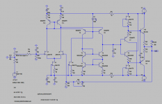
I did some tweaking again on one of the boards and added current mirrors on top of the LTP. Adding CM reduces 2nd harmonics a lot, both simulated and measured. The sound is a little sharper, but I've not listened to it enough to tell if it's more or less enjoyable. I've disliked CM in other amps, maybe it's just like Lumba Ogir says, it's all about harmonics😕.
Attachments
I don't get it 🙁 How is the folded cascode current defined if you use CM?
Did you try to use active load (ccs) folded cascode?
Did you try to use active load (ccs) folded cascode?
Hi Nelson,
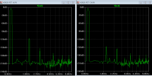
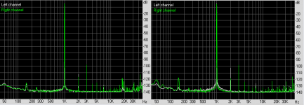
It's me again😀 ...If you stick CM on top of FC transistors, simulator will show identical voltage at T11/12 collectors, but in real circuit there will be some difference, especially as T12 have additional one Vbe drop...IMHO simple CM as yours is not a way to go with FC circuit. Stick with your AD797 discrete circuit, you are doing just fine. Image below is simed THD pattern from my discrete AD797, 2Vpp output, 300E to show what is possible from AD797 circuit in virtual word.

It's me again😀 ...If you stick CM on top of FC transistors, simulator will show identical voltage at T11/12 collectors, but in real circuit there will be some difference, especially as T12 have additional one Vbe drop...IMHO simple CM as yours is not a way to go with FC circuit. Stick with your AD797 discrete circuit, you are doing just fine. Image below is simed THD pattern from my discrete AD797, 2Vpp output, 300E to show what is possible from AD797 circuit in virtual word.
Nelson, Mihai is right. The design of the upper current mirror in your schematic <http://www.diyaudio.com/forums/attachment.php?s=&postid=1739711&stamp=1234201872> is problematic. You may want to redesign this current mirror so that it has double outputs and a single input, feed the input with a current source of the desired value, and feed each of the folded cascodes with one of the current mirror outputs.
Hint for Mihai's power amp: You can add a DC null control to such a current mirror configuration, which will enable the DC null to function (allowing the entire amp circuit to be direct-coupled) with a minimum of effect on the AC signal, with improvements to the sound quality.
Also, the present location of C7 may be a problem in real life, because it will allow RF energy injected from the output to short-cut directly to the input stage, without going through any low-pass filter. Better to insert C7 between the gate of J2 and the collector-collector junction of T6/T4 (so it forms a local NFB loop). A revision to the value of C10 may be appropriate if you do this.
regards and hth, jonathan carr
By altering R1/R2 or D1 I can get the current I want through the folded cascode. I've settled for 2 mA through each of T3/T4 in my amp. I'm not good at this so maybe I've got it all wrong. It measures well and seems stable though.roender said:I don't get it 🙁 How is the folded cascode current defined if you use CM?
Did you try to use active load (ccs) folded cascode?
The real amp actually shows identical voltage at the collectors of T11/T12. I read 0.0 mV on my DMM.aparatusonitus said:Hi Nelson,
It's me again😀 ...If you stick CM on top of FC transistors, simulator will show identical voltage at T11/12 collectors, but in real circuit there will be some difference, especially as T12 have additional one Vbe drop...IMHO simple CM as yours is not a way to go with FC circuit. Stick with your AD797 discrete circuit, you are doing just fine. Image below is simed THD pattern from my discrete AD797, 2Vpp output, 300E to show what is possible from AD797 circuit in virtual word.
This is more of a side track. I was just curious to hear an amp with lower 2nd harmonics. While it simulates and measures well, it has a piercing kind of sound. The sound of my discrete AD797 is smoother.
Your amp certainly looks impressive!
- Status
- Not open for further replies.
- Home
- Amplifiers
- Headphone Systems
- Folded cascode headphone amp