Thanks Fran yes to the jumper bars and the 0r jumpers. I'll post some pics tomorrow as I left them at work!


First thing I see @jimk04 is that you haven't populated R52 and R62 - I hope you have a few more 820r for that.
The "out" terminal in the middle of the board is to feed through to the stacker board. So if you are not using the stacker/filter, then you can ignore this completely. The output to preamp/whatever is taken from the out2 and gnd terminals near Q7/Q8.
Add those 2 resistors and let us know how it goes then.
Thanks for the input guys. Sorry I missed the obvious and to waste time...I seemed to have it on mind that they were for trimming. And thanks Vunce for the R3 call. That was actually the 'good' channel but I went over it.
So adding the 820r had definitely changed things! Now have a wandering 13....20 or is it 30mv on the L and 6 something V...yes V on the R. I definitely need to take stock and have another look at things. I'll give it some time and revisit with a clearer head. Not that I've been drinking yet!
So adding the 820r had definitely changed things! Now have a wandering 13....20 or is it 30mv on the L and 6 something V...yes V on the R. I definitely need to take stock and have another look at things. I'll give it some time and revisit with a clearer head. Not that I've been drinking yet!
6V seems too high....., go over it one more time....
Check that you have Q3 and Q4 in the correct spot - I can only see that they are oriented correctly but not that they are the right channel in the right spot if you know what I mean....
So one side is looking good, and after you sort it out, then the next step will be to test using a dummy resistor. Do you have an oscilloscope by any chance? A DMM will do, but if you have a scope, let us know.
Yes 6v seems massively high! Shall hopefully look it over tomorrow or Sunday.
I do have a scope.
I did double check all the Q locations and all seems well there. Thanks Fran. I don't expect a constant helping hand over the coming days being New Years and all...well I don't expect one at all. I appreciate your help whenever convenient.
I do have a scope.
I did double check all the Q locations and all seems well there. Thanks Fran. I don't expect a constant helping hand over the coming days being New Years and all...well I don't expect one at all. I appreciate your help whenever convenient.
Last edited:
One channel sorted, had about +20mV and 1meg in R65 swung it into negative so I put in 910k there and now have approx 2mV.
R channel still not playing ball. Have reflowed. I guess next I shall measure voltages over the resistors to ascertain currents flowing. What nodes would I be looking to check to see if the devices are working ? Or other tests?
Thanks again
R channel still not playing ball. Have reflowed. I guess next I shall measure voltages over the resistors to ascertain currents flowing. What nodes would I be looking to check to see if the devices are working ? Or other tests?
Thanks again
I assume you measure output at the source of Q7 (or drain of Q8) to Gnd.
1) Measure gate of Q7 to Gnd. If it is same as Q7 source, then the output buffer is OK.
2) Measure voltage across Riv. If it is not 0V, then something wrong in the current conveyor.
3) Measure voltage across all 4 current mirror resistors, if they are not equal then current mirror is at fault.
4) Measure voltage at I_in when not connected to DAC. If it is not less than a few mV, your input pair is at fault.
You have a working channel, so it is easy to compare what is correct and what is not.
Happy New Year to all,
Patrick
Last edited:
Hi Guys,
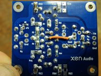
I've finally got around to slowly grinding away on my I/V build and have a few questions. On the top of the I/V boards there is a spot for two surface mount devices next to C3/C4 but there is no label on the boards and I see them populated in Frans build pics, I have attached a pic with them circled in red. What are they ?
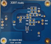
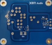
Also on the SK 25 Hz filter board the BOM mentions a Civ (Wima FKP2) but for the life of me I cannot find a Civ on the top or bottom of the board, pics attached. Any help would be greatly appreciated.
Thanks
I've finally got around to slowly grinding away on my I/V build and have a few questions. On the top of the I/V boards there is a spot for two surface mount devices next to C3/C4 but there is no label on the boards and I see them populated in Frans build pics, I have attached a pic with them circled in red. What are they ?
Also on the SK 25 Hz filter board the BOM mentions a Civ (Wima FKP2) but for the life of me I cannot find a Civ on the top or bottom of the board, pics attached. Any help would be greatly appreciated.
Thanks
Attachments
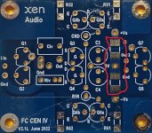
Those would be C1 and C2......On the top of the I/V boards there is a spot for two surface mount devices next to C3/C4 but there is no label on the boards and I see them populated in Frans build pics, I have attached a pic with them circled in red. What are they ?
Also on the SK 25 Hz filter board the BOM mentions a Civ (Wima FKP2) but for the life of me I cannot find a Civ on the top or bottom of the board, pics attached. Any help would be greatly appreciated.
Civ is on the main FC CEN IV boards - see just above your Riv on your first picture above. The reason it is listed in the S&K BOM separately is because if you are using those boards then you need a different value of capacitor fitted there (ie on the IV board) than if you are not using the S&K filter.
I hope that makes sense!!
It has already been explained in the article in post #1 what the criteria behind the choice of the cascode devices are.
As the those small signal MOSFETs are on a 1 year lead time, the question has been raised to replace them with bipolar transistors.
As much as you can trust simulations, here is the distortion spectrum with the original circuit :

And this is the same when replaced by bipolar transistors :

Patrick
As the those small signal MOSFETs are on a 1 year lead time, the question has been raised to replace them with bipolar transistors.
As much as you can trust simulations, here is the distortion spectrum with the original circuit :
And this is the same when replaced by bipolar transistors :
Patrick
i am about to complete soldering the pcbs and i have a question ..
i ordered the matched mosfets with R1-4 too .
What about Rt3 and Rt4 ? i cannot find any information about these .
Do i follow the default values as in the user guide ? i see some people 's images
show different values ..
i ordered the matched mosfets with R1-4 too .
What about Rt3 and Rt4 ? i cannot find any information about these .
Do i follow the default values as in the user guide ? i see some people 's images
show different values ..
- Home
- Source & Line
- Digital Line Level
- Folded Cascode CEN IV with fixed Rails