Member
Joined 2019
1) What is the advantage of horizontal guiding wheels ? If wheels are vertical we can remove the boat and have less friction ?
I tried this, but could not achieve enough low friction. The reason: friction is roughly proportional to the load on the wheel bearings. In the 'vertical' case the load equals 30 g force - the whole cartridge. In the 'horizontal case it equals 2-3 g - the magnet force + the skating.
2) Is magnet necessary to hold the wheels against the wall ? Wouldn't Stylus drag keep the wheels in touch with the wall ?
It would during the playback, but not during "stylus up" movements.
3) Would a curved bottom surface of the boat lower the friction ? it will have less contact with water.
The boat friction with the water is already very low - below 1 dyne = below 1 mg force. The wheels bearings friction is the main component. The solution is to replace the existing bearings with more fine ones.
I will post you soon an older clip with the 'vertical' experiments.
Member
Joined 2019
Member
Joined 2019
Member
Joined 2019
Member
Joined 2019
Floater
Hi,
S.E. Grimm has done some nice work on this, together with descriptions, calc etc
Have fun
Vinyl Turntable Equipment: DIY tangential tonearm
Best,
Coolerooney
Hi,
S.E. Grimm has done some nice work on this, together with descriptions, calc etc
Have fun
Vinyl Turntable Equipment: DIY tangential tonearm
Best,
Coolerooney
Member
Joined 2019
Member
Joined 2019
Hiten, Hi again.
I thought again about your remark related to the increased friction due to the additional magnet force. It is absolutely true that for smooth and linear boat movements when stylus is up the magnet is absolutely necessary. But this does not mean that the magnet has to be there while the stylus is down. I did some experiments and found that playback without magnet, only with the roughly 600 dyne tracking force, is quite stable. In this case the wheels friction should theoretically go down about 3 times - to nearly 10 dyn, so the total friction (the pickup arm one added) would be about 15 dyne. I will work further on it, but I post you a drawing with the basic idea. I have to add that the Shaft Up-Down mechanism may be independent from the Stylus Up-Down, so that small shaft Ups may serve for magnet attraction adjustment.
New Magnet System.png - Google Drive
Last edited:
Yes thats what I thought. This design basically replaces vertical load with magnet load. How much less I cant tell being a newbie. Besides I dont understand formulas and maths.Hiten, Hi again.
I thought again about your remark related to the increased friction due to the additional magnet force.
You can decrease the magnet strength and still use it for comfortable stability level.
You have worked hard on design so trying to comment with my rudimentry understanding. Still trying to understand boat/bearing friction. Also how to still lower the bearing friction. With no measuring equipment and understanding of physics and maths what I would have done is taken a cheap cartridge. with moderately off center+warped record and torture test the design. if it remains stable there is no doubt at minute level it will still further be. I will post some thoughts when time permits.
Regards
...also a jewel bearing instead of regular bearing will be good isn't it ? less play and friction. A little more tight mechanical ground.
Member
Joined 2019
Hiten, I will describe soon in details the new magnet system, so a reply briefly:
I calibrated my neodymium magnet with a steel shaft, so I know what is the attractive force as a function of the distance between the two objects.
Magnet Calibration.png - Google Drive
It comes out that the designed system allows the adjustment of the magnetic force within nearly an order of magnitude: 2040 - 250 dyne. This is quite sufficient.
New Magnet System 2.png - Google Drive
As about "a jewel bearing instead of regular bearing" - yes, it can be a fine solution, if only the mass of those two jewel bearing systems is not too big. I still think that a top-level classic ball bearing of affordable price may be the best solution.
Member
Joined 2019
A compilation of recent jazz recordings with TTT. The LPs are made in USSR and DDR during the 1980ies. The initial digital records are edited with my standard procedures: Sharp cut below 30 Hz, Brian Davies Click Repair, Adobe Audition Noise reduction, Cartridge equalization (AT95EX) and Levels normalization.
The file is in FLAC 48 kHz 32 bit format. To listen, press "Play anyway".
TTT Mixture.flac - Google Drive
The file is in FLAC 48 kHz 32 bit format. To listen, press "Play anyway".
TTT Mixture.flac - Google Drive
Solid Mechanical coupling of tonearm is always preferable.
But as others have said about water changing height of tonearm (probably by record warps) and friction of float moving across linearly see if following is worth any merit.
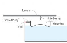
What I have done is put a v rail (Shown in red) acrosss the glass wall and v shaped pulley will slide on it. This makes a comfortably good coupling to restrict any movement vertically while tonearm moves across. The boat is curved below and is hollow so only edges touches the water thereby reducing friction. Will this improve the working ?
Best regards.
But as others have said about water changing height of tonearm (probably by record warps) and friction of float moving across linearly see if following is worth any merit.
What I have done is put a v rail (Shown in red) acrosss the glass wall and v shaped pulley will slide on it. This makes a comfortably good coupling to restrict any movement vertically while tonearm moves across. The boat is curved below and is hollow so only edges touches the water thereby reducing friction. Will this improve the working ?
Best regards.
Attachments
Member
Joined 2019
Hi, Hiten. This type of boat directing in theory is better than the original one of the Ivanov, which I follow too. This may become true in practice if:
1. We have enough low noise of the contact rail - pulley. If both are metal, the noise will be (I think) higher than in the case plexiglass - glass. But a couple steel - Teflon could be quite silent. BTW, what are the conus angles of your rail and pulley?
2. We need also low friction of the pulley rotation. No matter what the bearings are, the friction acting to the boat will decrease with the increasing of the pulley diameter, so it is good to mount the pulley on the top of the boat and make its diameter as big as possible. In my case D = 40 mm. This will reduce also the length of the tonearm, which is a desirable issue.
I think that it is fine to experiment with boat profiles to lower the friction boat - water. We must remember that this friction has to be low in the direction of the principal boat movement, but in the other 2 directions - front-back and up-down higher values may be preferable. I like your catamaran idea, it is likely that it conforms with the goal described in the previous sentence. But, once again, I have to assure you that even the most 'trivial' boat profiles have boat-water friction levels of about 1 dyne, which is a VERY low value. The main friction problems arise from the pulleys.
I am ready with my new magnet stabilizer device and will post a clip later today.
Last edited:
Member
Joined 2019
Member
Joined 2019
Hiten, a second answer to your last post.
If we compare my leading system and yours, they are both "solid" in the direction to the disk. In the vertical direction my construction is floating and yours - "semi-floating": you got a rotational floating around the rail-pulley contact point. So, the vertical fluctuations of the boat will be reduced roughly by 50%, but not disappear.
BTW, your version will also need the magnet 'support' in stylus up position - it is equally instable without a force towards the disk.
As I already have said, those "others" neglect totally a lot of fine experimental data I provided about the boat position variations in all dimensions:
1. Along the tangential path: the boat follows the eccentricity movements of the disk groove, so the related angular error is much lower than in the case of a pivoted arm.
2. Towards the disk: the average value of the measured deviations is ±16 microns.
3. The average value of vertical fluctuations is ±33 microns
4. The angular deviation of the boat from verticality is within ±0.017o (degrees).
The neglection of experimental data, as if they did not exist at all, is considered as a quite btutal behavior in the scientific world, that's why I refused any further discussion. And not because "I can't stand the heat".. I am in the kitchen since 1968 and I have a 'classical' pivot DIY turntable published in 1975:
Takyphone.JPG - Google Drive
Solid Mechanical coupling of tonearm is always preferable.
If we compare my leading system and yours, they are both "solid" in the direction to the disk. In the vertical direction my construction is floating and yours - "semi-floating": you got a rotational floating around the rail-pulley contact point. So, the vertical fluctuations of the boat will be reduced roughly by 50%, but not disappear.
BTW, your version will also need the magnet 'support' in stylus up position - it is equally instable without a force towards the disk.
But as others have said about water changing height of tonearm (probably by record warps) and friction of float moving across linearly see if following is worth any merit.
As I already have said, those "others" neglect totally a lot of fine experimental data I provided about the boat position variations in all dimensions:
1. Along the tangential path: the boat follows the eccentricity movements of the disk groove, so the related angular error is much lower than in the case of a pivoted arm.
2. Towards the disk: the average value of the measured deviations is ±16 microns.
3. The average value of vertical fluctuations is ±33 microns
4. The angular deviation of the boat from verticality is within ±0.017o (degrees).
The neglection of experimental data, as if they did not exist at all, is considered as a quite btutal behavior in the scientific world, that's why I refused any further discussion. And not because "I can't stand the heat".. I am in the kitchen since 1968 and I have a 'classical' pivot DIY turntable published in 1975:
Takyphone.JPG - Google Drive
Last edited:
I understand. Please dont take my picture literally for Conus angle and pulley position etc. This was just rough idea drawing. I am just thinking about if your design can have option/mods/improvements. The V rail just holds the pulley so as there is no vertical movement. If idea is worth exploring the position etc. can be arranged. Also I read somewhere there are coatings available which repels water I wonder if it can be used in curved bottom surface.
Regards.
Regards.
Wow!
Sorry. I just have to say wow. So very educational. All those unknown recordings to check out on your channel. I hope i get time and skills to build one when I retire
Sorry. I just have to say wow. So very educational. All those unknown recordings to check out on your channel. I hope i get time and skills to build one when I retire
The tip of the stylus, the point where the pulleys touch the glass and the pivot of the tonearm should be all on the same horizontal plane to avoid unwanted torque.
- Home
- Source & Line
- Analogue Source
- Floating Tangential Tonearm