I don't understand why you put "with particular reference to phono preamplifiers" in the title. The article doesn't say anything about the effect of RIAA weighting, and its results are useable for any amplifier that is sensitive to the valve's voltage noise.
I was concerned with the the true, unweighted noise of valves. RIAA eq is just another sort of weighting. Provided you know the true unweighted noise, you can apply whatever kind of weighting you like after the fact (e.g. in a spreadsheet), and that is up to the whim of the reader. If I'd included RIAA weighting then no doubt other readers would complain that I hadn't included CCIR or A-weighting. I rather meant to give the reader an idea of how to minimise the unadulterated noise, which is bound to improve the weighted noise too! 😎
My reference to phono amplifiers was to show that for common cartridges you don't have to worry about grid current as a source of noise. Also, putting "phono" in the title is likely to draw more attention than just "triode noise"! 😉
Anyway, if the noise is purely white, then RIAA eq will result in about 3.1dB improvement in the measured EIN. But as you add more flicker noise, this RIAA advantage shrinks. I haven't done the calculation, but I suspect that if you're unlucky enough to get a corner frequency up around 10kHz the RIAA advantage will be a fraction of a dB (I am assuming the same total noise to start with, not the same total white noise plus ever increasing amounts of pink).Therefore, since you can't predict flicker noise with much accuracy, I personally do not think it is worth relying of the RIAA advantage for anything.
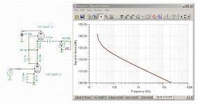
In fairness, the 6SN7GT was running @8mA using the depletion MOSFET CCS, so I reduced it to 5mA. The AP loads the circuit with 100K so running the passive anode load vs the active CCS didn't seem quite fair.
I changed the passive components to 47K as the anode resistor, 470R+220uF for the cathode, which came in just a bit over 5mA. Ran the test 5X for each setup, RMS'd the values, adjusted for gain and come up with the following:
I changed the passive components to 47K as the anode resistor, 470R+220uF for the cathode, which came in just a bit over 5mA. Ran the test 5X for each setup, RMS'd the values, adjusted for gain and come up with the following:
An externally hosted image should be here but it was not working when we last tested it.
I was concerned with the the true, unweighted noise of valves. RIAA eq is just another sort of weighting. Provided you know the true unweighted noise, you can apply whatever kind of weighting you like after the fact (e.g. in a spreadsheet), and that is up to the whim of the reader. If I'd included RIAA weighting then no doubt other readers would complain that I hadn't included CCIR or A-weighting. I rather meant to give the reader an idea of how to minimise the unadulterated noise, which is bound to improve the weighted noise too! 😎
My reference to phono amplifiers was to show that for common cartridges you don't have to worry about grid current as a source of noise. Also, putting "phono" in the title is likely to draw more attention than just "triode noise"! 😉
Anyway, if the noise is purely white, then RIAA eq will result in about 3.1dB improvement in the measured EIN. But as you add more flicker noise, this RIAA advantage shrinks. I haven't done the calculation, but I suspect that if you're unlucky enough to get a corner frequency up around 10kHz the RIAA advantage will be a fraction of a dB (I am assuming the same total noise to start with, not the same total white noise plus ever increasing amounts of pink).Therefore, since you can't predict flicker noise with much accuracy, I personally do not think it is worth relying of the RIAA advantage for anything.
Weighting changes the noise optimum. The effect of white and pink noise on the total (integrated) output noise are changed to different degrees, so the bias current that minimises the weighted total noise is different from the bias current that minimises the unweighted total noise. That being said, I agree that weighting can be done after the fact, using your fitted equations for white and 1/f noise as a function of bias current.
I hope people who look for triode noise data for some other low-frequency application involving lowish source impedances are not scared off by the "phono" in the title. Your paper is applicable to much more than just phono amplifiers.
This is very good work but one thing puzzles me. Why has the bandwidth been restricted to 200Hz to 20KHz?
Cheers
Ian
Cheers
Ian
This is very good work but one thing puzzles me. Why has the bandwidth been restricted to 200Hz to 20KHz?
It's really hard to get all the power line/mains components out when measuring this low.
I super-imposed the ITU/CCIR-486 noise sensitivity data on the previous chart. Folks certainly more expert than me feel ITU/CCIR-4846 to be more accurate than A-weight filtering when it comes to sensitivity to "hiss":
An externally hosted image should be here but it was not working when we last tested it.
A lot of the information on tube noise was crafted in WW-II for HF, VHF and UHF.
I've done a couple of calculations to link Merlin's data to RIAA amplifier optimisation. See the attachment.
You are, I assume, going to send the letter to the JAES. Nice work.
No, I have no intention to send it to the JAES. I'm in the process of writing an article about RIAA noise optimisation for Linear Audio, or actually, I thought I had finished writing an article about RIAA noise optimisation, but now that I've read Merlin's paper, I'm going to re-write the section about valve amplifiers.
The assumption I've made that valves follow Child's law is actually too inaccurate. A more practical approach is to calculate the equivalent input noise voltage density at 1169 Hz using the equations from Merlin's paper and then try a couple of bias current/transconductance combinations (reading of the transconductance from a transconductance versus current graph in the valve datasheet).
It's really hard to get all the power line/mains components out when measuring this low.
I know, I have been measuring tube noise for several years. dc heaters, screened boxes and extensively filtered HT are essentials.
I super-imposed the ITU/CCIR-486 noise sensitivity data on the previous chart. Folks certainly more expert than me feel ITU/CCIR-4846 to be more accurate than A-weight filtering when it comes to sensitivity to "hiss":
Agreed. My Lindos test set uses this weighting curve for its noise measurements.
A lot of the information on tube noise was crafted in WW-II for HF, VHF and UHF.
Which is why it is not much help for audio design.
Cheers
Ian
Merlin, are the ECC83-data in your table 1 for two halves in parallel, like figures 4 and 5, or for only one half of an ECC83?
They apply for parallel connection.Merlin, are the ECC83-data in your table 1 for two halves in parallel, like figures 4 and 5, or for only one half of an ECC83?
Here are figures I got for some other types (single triode). However, these are from a very small sample size (only two bottles of each type) so don't take them too seriously:
ECC85:
sigma = 1
K = 1.1 x 10⁻¹³
PCC189:
sigma = 0.6
K = 2.2 x 10⁻¹³
6N6P:
sigma = 0.8
K = 3 x 10-14
Last edited:
If I did the calculation correctly, that means that a single ECC83 triode has the same sigma, but twice the K you put in your table:
S(in)=4 k 0.644 Tk gm/sigma + K IA^2/f
Single triode:
4 k 0.644 Tk gm_single/sigma + K_single IA_single^2/f
Two in parallel must have twice the drain current power spectral density of a single triode:
4 k 0.644 Tk gm_double/sigma + K_double IA_double^2/f = 2*(4 k 0.644 Tk gm_single/sigma + K_single IA_single^2/f)
With gm_double=2*gm_single and IA_double=2*IA_single:
4 k 0.644 Tk gm_double/sigma + K_double IA_double^2/f = 4 k 0.644 Tk gm_double/sigma + (K_single/2) IA_double^2/f
Hence, K_single/2=K_double, or K_single=2 K_double.
They apply for parallel connection.
Here are figures I got for some other types (single triode). However, these are from a very small sample size (only two bottles of each type) so don't take them too seriously:
ECC85:
sigma = 1
K = 1.1 x 10⁻¹³
PCC189:
sigma = 0.6
K = 2.2 x 10⁻¹³
6N6P:
sigma = 0.8
K = 3 x 10-14
Hi Merlin,
I am building preamp for ribbon mic. It has to be very quiet because input signal is extremely low, like 100 times lower than LOMC.
Currently I've built it with input stage based on 6S45P-E mu-follower ( preceded with SUT). But I am not satisfied with its flicker noise.
I've got your article. It is very helpful. Especially with selection of proper Ia and V heater.
But unfortunately there is no data for 6S45P (also often called 6C45P). Do you have any plans to test this one? It would be nice to know its Sigma and K.
Also there is is mentioned "For minimum noise the input stage should be passively loaded.". Do you have any data on this matter, like comparing with mu-follower.
They apply for parallel connection.
Here are figures I got for some other types (single triode). However, these are from a very small sample size (only two bottles of each type) so don't take them too seriously:
ECC85:
sigma = 1
K = 1.1 x 10⁻¹³
PCC189:
sigma = 0.6
K = 2.2 x 10⁻¹³
6N6P:
sigma = 0.8
K = 3 x 10-14
Thanks for writing a great article! Do you plan to post or publish the sigma and K values for more tubes in the near future? It seems to be a time consuming process to manually adjust sigma and K until the predicted curve fits the data.
I find it interesting that the noise curve for the 12AX7, for example, reaches a minimum right around 1.5mA plate current, just where a lot of people historically operate that tube.
Also, the corner frequency for the noise spectrum seems to shift based on the plate current for lower Gm tubes (lower current shifts the corner frequency lower) but the opposite appears to be the case for the ECC88 (increasing plate current lowers the corner frequency), a high Gm tube (your figure 7). Am I seeing that correctly? Do you think this is the case with most of the frame grid, high Gm tubes? Thanks.
Last edited:
Sorry, no, it has now taken a backseat to everything else I do! Plus I have no desire to spend a lot of money on quantities of tubes I may never use... 🙄 I think the point is made though; sigma and K are not likely to vary far beyond the range I discussed, so the generic figures of 0.6 and 10^-13 should get you into the ballpark where you can predict the noise optimum with reasonable accuracy. Any predictions are just as likely to be limited by your estimations of gm and the natural variance between samples, as they are by knowing sigma and K.Thanks for writing a great article! Do you plan to post or publish the sigma and K values for more tubes in the near future?
I haven't looked at the mu-follower, but it should be easy enough to simulate a noisy mu-follower in SPICE and so prove whether it worsens the EIN or not.Also there is is mentioned "For minimum noise the input stage should be passively loaded.". Do you have any data on this matter, like comparing with mu-follower.
Last edited:
I haven't looked at the mu-follower, but it should be easy enough to simulate a noisy mu-follower in SPICE and so prove whether it worsens the EIN or not.
Some quick simulations show that the EIN of a mu-follower is OK, because it is equivalent to a gain stage followed by a cathode follower, so the gain stage dominates as usual. An SRPP (lower cathode bypassed) was worse by 1.2dB. These all assume identical triodes operating under identical anode current and bias voltages.
Last edited:
Thanks, Merlin. I am curious have you added your noise model to existing models of tubes, or it is separate "tube noise" component? Could you explain or/and post your SPICE here? Thanks!Some quick simulations show that the EIN of a mu-follower is OK, because it is equivalent to a gain stage followed by a cathode follower, so the gain stage dominates as usual. An SRPP (lower cathode bypassed) was worse by 1.2dB. These all assume identical triodes operating under identical anode current and bias voltages.
Some quick simulations show that the EIN of a mu-follower is OK, because it is equivalent to a gain stage followed by a cathode follower, so the gain stage dominates as usual. An SRPP (lower cathode bypassed) was worse by 1.2dB. These all assume identical triodes operating under identical anode current and bias voltages.
What did you use to bias the lower cathode of the mu-follower?
Bypassing the lower cathode biasing resistor of a mu-follower appears to increase the SNR by a lot.
Attachments

I simply added a current source in parallel with each triode, set to generate a 2nA sine wave (a typical figure). For resistor noise I used a voltage sinewave source in series with the relevant component. Then I monitored the output voltage signal when each individual noise source is present in turn, then take the root of the sum of the squares to find the total that would exist if all the noise sources were present.Thanks, Merlin. I am curious have you added your noise model to existing models of tubes, or it is separate "tube noise" component? Could you explain or/and post your SPICE here? Thanks!
Noiseless battery (i.e. fully bypassed).What did you use to bias the lower cathode of the mu-follower?
- Status
- Not open for further replies.
- Home
- Amplifiers
- Tubes / Valves
- Flicker Noise dominates triode noise in audio (AES)