Merlin could you take a look?
Sorry, SPICE langauge is a mystery to me too!
From various sources I've found that flicker noise is already embedded into SPICE2 diode model - take a look at parameters KF (flicker noise coefficient) and AF (flicker noise exponent).
Many tube models use diode model. So may be it is possible to add these parameters to there?
I missed this post earlier, which seems to be at the source of your line of questions. Please bear in mind that the diode model used within the tube models is merely there to simulate the grid current when Vgk > 0, which for hi-fi application, should never occur. In fact, it is usually advisible to keep Vgk < -0.7V to make sure that the grid does not conduct at all. So those noise/temperture parameters for the diode are not useful for modeling noise for the tubes. As mentioned before, if you want to model the tube noise properly, you need to provide the codes yourself, since no one has done so yet - I was wrong, even Excem's models did not model noise.
A minor point on "7 0" again, it simply means that a 1G Ohm resistor, i.e., nearly an open circuit is in parallel with the voltage source at node 7, so it really does not do anything to the tube's current, it is just there to fool the SPICE into convergence.
Last edited:
May be for some models. But for the model that I've posted here the diode model is used to model grid-cathode relation. It somehow works for negative Vgk also. I've set a signal on grid that never goes to positive region, and changed KF parameter in call of D sub-model - it changed total noise in LF area, increasing its flicker part. You can try it yourself.Please bear in mind that the diode model used within the tube models is merely there to simulate the grid current when Vgk > 0, which for hi-fi application, should never occur. In fact, it is usually advisible to keep Vgk < -0.7V to make sure that the grid does not conduct at all. So those noise/temperture parameters for the diode are not useful for modeling noise for the tubes. As mentioned before, if you want to model the tube noise properly, you need to provide the codes yourself, since no one has done so yet - I was wrong, even Excem's models did not model noise.
I have a doubt that grid-cathode is a right place to add flicker noise into the model, I think it should be in cathode-plate (7 0). but there is just math expression that does not call the native SPICE diode model. I do not know how noise component can be added there. May be it is possible if there is a good random() function in SPICE math function set. I should take a look if that exists.
But still, even if gk is not a good place to insert noise here, but it still works, resulting in modeling of tube flicker noise, may be this trick still can be used?
By the way, SPICE diode model has some limitation for temperature parameter.
It fails for T >100. So it is not useful here.
Yes, I tried to place {mu/gm} there, nothing really changes.A minor point on "7 0" again, it simply means that a 1G Ohm resistor, i.e., nearly an open circuit is in parallel with the voltage source at node 7, so it really does not do anything to the tube's current, it is just there to fool the SPICE into convergence.
May be for some models. But for the model that I've posted here the diode model is used to model grid-cathode relation. It somehow works for negative Vgk also.
No doubt it works, but that's not the intent, the origin of using a diode to model the grid current in tubes was from Dr. Leach's paper if I am not mistaken, where he stated: "A series solid-state diode D1 and resistor Rg approximately model the grid circuit for Vgk > 0." Or in other words, the diode model should not be relied on for Vgk < 0, which is the normal operation of the tube! That's why Igk is usually a meaningless figure for most of the triode SPICE models you find. If you want a more accurate representation, you need to either get the proper model (see the Sticky SPICE Model thread) or build your own.
Thanks for working on this. I put your 6C45P-E model into a circuit in Tina and it does produce different noise curves, though they still seem unrealistic to me. I mean, what circuit has a SNR of 180 dB? None that I know of.
yes it may be unrealistic because parameter values are so. It was just an illustration of idea to use diode's flicker parameters.
As jazbo8 said diode there is for some secondary purpose, but I do not think that diode could serve also an another secondary purpose, like generating flicker noise.
I am reading now about LTSpice rand(), random() and white() functions. Hope they can be used to add some white noise to voltage or current source in tube.
I am trying them now, I see they greatly slow down computations. 🙁
I think the best methode to model tube noise was outlined by Merlin on the ribbon-mic thread, you use multiple voltage and/or currrent sources with their respective equivalent resistances then run the simulation to get the sum for the total noise - in effect, you deconstruct the tube model into seperate parts to account for the various types of noise.
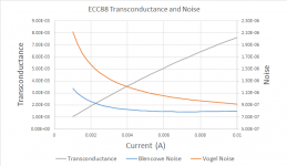
Figure 6 in the article relates Transconductance and EIN voltage with Ia for a 6J52P.
Taking the data from the Phillips data sheet for 6922/ECC88 (sigm =0.6, K=6.2*10^-14, and plugging the numbers into Eurequa I get a simple quadratic equation which relates transconductance to current. From this I derive the equivalent resistance with current (Vogel uses a static value and assumes that the two triodes are connected in parallel.)
I added in the grid load resistor noise, for both, but it can be eliminated. (This is why the graph differs from figure 4.)
Attachments
- Status
- Not open for further replies.
- Home
- Amplifiers
- Tubes / Valves
- Flicker Noise dominates triode noise in audio (AES)