Hello,
I plan on building an FLH subwoofer for a single 12" driver and I am stumbling on a few basics pertaining to getting started in Hornresp. I am a first timer, but have spent enough time with Hornresp to understand most of it through modelling and altering others' works.
Where I am having problems with creating a new design for myself have to do with not understanding flare rates per segment or target FTA... I have no idea what I should be beginning with (or shooting for) optimally, because I don't know what the flare tangent angle relates to.
Is there an FTA relationship to sound wave lengths in that flare angle? Volume of the segment(s) and/or total volume of the horn? Some combination of those (and other factors such as compression ratio etc.) factors?
Its really bugging me so I have stopped fiddling around aimlessly in Hornresp until I can better understand the WHY for, before taking on the HOW to.
Thank you for stopping by!
outline your goals.
The most important is your desired low frequency cuttoff (which will then tell you the approximate length of your horn).
Next, I decide on a target sensitivity for the low corner.
then I rough out my basic horn shape and determine a rough externall dimensions
The most important is your desired low frequency cuttoff (which will then tell you the approximate length of your horn).
Next, I decide on a target sensitivity for the low corner.
then I rough out my basic horn shape and determine a rough externall dimensions
The two main parameters are lenght (1/4 wavelength) so a 1.5 m horn has a cutof at about 50 Hz. Next thing is mouth area, the larger the smoother the horn response. A really small mouth and the thing is just a quarter wave pipe not a horn any more. How large mouth is large enough is dependent on radiation angle. Having the horn in suspended on a flag pole you would need a really large mouth area, having the horn on the ground and half the area would suffice. Adding a backwall to that and the needed area is halved again, and adding a side wall the same thing. So a corner horn or at least close to a corner need 1/8 the mouth area of a free space horn. Flare rate and all that does not matter much for short horns, as their shortcomings ins lenght and mouth area owershadow the effect of different taper flares.
So FTA is not a key element to focus on in the beginning, rather its shown as a result of the design. So its informational more than anything..? Thats why its shown in Hornresp grayed out then... thanks, I worried that I should better understand that.
Thanks for the PAR tip too. That could be critical me thinks!
So this is all great advice! As I understand so far I must first define my goals for a passband response from a low knee to high freq falloff. Then take that low knee frequency (1/4) wave length to define the minimum path length of the horn. Mouth size should be considered along with path length as well, as they are interdependent. Large mouth insures greater coupling with the room environment if placed along a wall or near (or as part of?) a corner. Got it. So far this sounds simple enough and perhaps my ignorance is blissful after all! 😀
Ok, here are my goals:
This is for music only. No movies ever. I have some music that plumb the depths to around 16 hz (or lower, how would I know?).
Physically I want to limit the overall length and width of the cabinet to fit within common 4 x 8 feet sheets of plywood. Height of the cabinet is limited to approximately 24 inches, so that I can easily roll the beast through the front door of my house after its built and later, because I want to roll it out onto my porch for listening while working long summer days outdoors. Nearest neighbor is 1.25 miles away, so I can get away with a wee bit of excessive noise. So, max overall cabinet size is 4' x 8', with some flexibility on the 2 foot max height.
My goal for response is from ~18 - 60 Hz or better, so roughly about 2 octaves in range me guesses? I'd really like to reach 16 hz at the bottom, but if an F3 of 16 Hz is the best I can get thats OK. The horn will be put against a wall (near a corner but not firing into it) while indoors. The room is about 14 feet x 26 feet with a hallway entering the room near (perpendicular to) the horn mouth. The mains speakers that I cross over to at the top should not be considered as being a factor for this design. Like everyone else I long for the mostest efficiency, longest extension, consuming leastest power, while also expending the leastest!
Now here is the fly in the ointment. I have an old car audio 12" driver that I want to use. It is less than ideal but if I have to buy a new Pro Audio driver for this project, then its not going to get done right away. The driver I have is an Image Dynamics IDMAX12D2 V2.
T/S params as taken from a DUMAX report from Adire audio:
Fs - 27.66 hz
Qes - .5118
Qms - 2.1276
Qts - .4125
Vas - 85.0009 liters
Sd - 530 sq cm
Re - 4.136 ohms
Mmd - 146.85 g
Cms - .215251 mm/N
Rms 12.5621
BL - 14.6971 N/A
Xmax - 21.9 mm (70% BL)
PE - 1000 watts RMS
LE is not available but I expect it to be a bit high given the era this driver was made. Its a ~2" voice coil with no shorting rings. Stiff, light cone with narrow surround. The sound quality, uncommon for a driver of this type is most excellent with very, very low distortion. Seriously it is quite good! Power handling is actually about 500w rms, but its never seen over 250w yet and likely never will. Gotta keep costs down so this is where I hope to do that.
Am I leaving anything out...? This is enough for one post, I feel like I'm writing a book. I'll get started with what I understand so far. I'm sure there will be more stumbles but I am determined to complete this.
Thank you all for your help so far!
Thanks for the PAR tip too. That could be critical me thinks!
So this is all great advice! As I understand so far I must first define my goals for a passband response from a low knee to high freq falloff. Then take that low knee frequency (1/4) wave length to define the minimum path length of the horn. Mouth size should be considered along with path length as well, as they are interdependent. Large mouth insures greater coupling with the room environment if placed along a wall or near (or as part of?) a corner. Got it. So far this sounds simple enough and perhaps my ignorance is blissful after all! 😀
Ok, here are my goals:
This is for music only. No movies ever. I have some music that plumb the depths to around 16 hz (or lower, how would I know?).
Physically I want to limit the overall length and width of the cabinet to fit within common 4 x 8 feet sheets of plywood. Height of the cabinet is limited to approximately 24 inches, so that I can easily roll the beast through the front door of my house after its built and later, because I want to roll it out onto my porch for listening while working long summer days outdoors. Nearest neighbor is 1.25 miles away, so I can get away with a wee bit of excessive noise. So, max overall cabinet size is 4' x 8', with some flexibility on the 2 foot max height.
My goal for response is from ~18 - 60 Hz or better, so roughly about 2 octaves in range me guesses? I'd really like to reach 16 hz at the bottom, but if an F3 of 16 Hz is the best I can get thats OK. The horn will be put against a wall (near a corner but not firing into it) while indoors. The room is about 14 feet x 26 feet with a hallway entering the room near (perpendicular to) the horn mouth. The mains speakers that I cross over to at the top should not be considered as being a factor for this design. Like everyone else I long for the mostest efficiency, longest extension, consuming leastest power, while also expending the leastest!
Now here is the fly in the ointment. I have an old car audio 12" driver that I want to use. It is less than ideal but if I have to buy a new Pro Audio driver for this project, then its not going to get done right away. The driver I have is an Image Dynamics IDMAX12D2 V2.
T/S params as taken from a DUMAX report from Adire audio:
Fs - 27.66 hz
Qes - .5118
Qms - 2.1276
Qts - .4125
Vas - 85.0009 liters
Sd - 530 sq cm
Re - 4.136 ohms
Mmd - 146.85 g
Cms - .215251 mm/N
Rms 12.5621
BL - 14.6971 N/A
Xmax - 21.9 mm (70% BL)
PE - 1000 watts RMS
LE is not available but I expect it to be a bit high given the era this driver was made. Its a ~2" voice coil with no shorting rings. Stiff, light cone with narrow surround. The sound quality, uncommon for a driver of this type is most excellent with very, very low distortion.
Seriously it is quite good! Power handling is actually about 500w rms, but its never seen over 250w yet and likely never will. Gotta keep costs down so this is where I hope to do that.Am I leaving anything out...? This is enough for one post, I feel like I'm writing a book. I'll get started with what I understand so far. I'm sure there will be more stumbles but I am determined to complete this.
Thank you all for your help so far!
May I ask for help again... already! I haven't enough experience to weigh compression ratio demands in an FLH, but it seems to me like very high compression ratios in a horn are akin to attempts to force round pegs into square holes. I feel that a nominal 3:1 compression ratio should be plenty high enough if a design is not being overly compromised. Am I on the right track?
It seems like high compression ratios (4-5 to 1 and higher) are just introducing excessive force into the horn where better design practice should be the applied, rather than resorting to using a lot more force on it. Am I wrong about this? No point in overloading the driver and motor as that introduces early and certain distortion, correct?
Thanks again.
Darn it I thought of something else. I plan on folding this horn myself. Since I have no folding experience I thought I would draw out the Hornresp results on paper sized to about 1/2 or 1/3 scale, or as large scale as is practical. Sketchup is another learning curve I don't intend to pursue...
I have been reading a lot about folding and I really like the advice given by "Just a guy" here on these forums and elsewhere that he has posted. He talks about an "Advanced Centerline method" that yields more accurate folding than the more common method. So I hope to use his method for folding and I figure paper drawings may be my best bet to accomplish that.
Can I do it on a flat, scaled paper model or do I need to use software?
Horns have been designed for hundreds of years prior to software. If you find lofting easier drawing by hand (as I still do..) go for it.Can I do it on a flat, scaled paper model or do I need to use software?
Considering the excursion capability and light cone, 3 to 1 compression ratio would be on the high side, though if you don't plan on using more than 250 watts, 3/1 should be no problem.
Considering the Fs of 28 Hz, and your desire for an 18 Hz low corner, you may want to consider a tapped horn design, or at least compare TH to FLH of the same net volume.
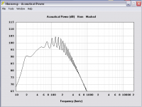
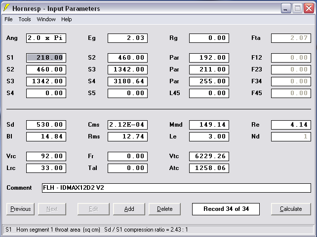
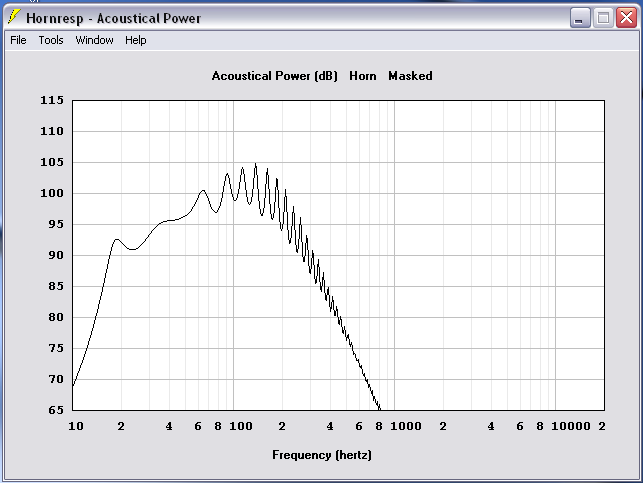
I am going to try to show some early work here if I can figure out how to link an image. This HR response is from a smaller ~550ish liter or so horn than I am planning now, using my IDMAX12 driver. I decided this cab was terribly inefficient and I could do better by making a larger cabinet. Its ugly on the bottom and top and very weak looking. So I scrapped that design and am now starting over from scratch. Target size is now larger at 4' x 8' x ~2'.
Do you guys do a total volume calculation of your target cabinet size, then reduce that available volume by a percentage (say about 20%?) to account for internal baffling, driver box and horn adapter, etc.? Thats what I'm doing cause I don't know any better. Hopefully the space will be used and not wasted when I get a good looking result.
Thanks.
Aargg... image may not be showing but hopefully clickable. Gotta go learn about this I guess.
An externally hosted image should be here but it was not working when we last tested it.
Do you guys do a total volume calculation of your target cabinet size, then reduce that available volume by a percentage (say about 20%?) to account for internal baffling, driver box and horn adapter, etc.? Thats what I'm doing cause I don't know any better. Hopefully the space will be used and not wasted when I get a good looking result.
Thanks.
Aargg... image may not be showing but hopefully clickable. Gotta go learn about this I guess.
So FTA is not a key element to focus on in the beginning, rather its shown as a result of the design. So its informational more than anything..? Thats why its shown in Hornresp grayed out then... thanks, I worried that I should better understand that.
I used to know what FTA was but I forgot, it might be more important in higher frequency horns but it's not something I even look at.
Thanks for the PAR tip too. That could be critical me thinks!
it's quite important when it comes time to fold but in the preliminary stages of finding out potential performance it's not important at all.
Then take that low knee frequency (1/4) wave length to define the minimum path length of the horn. Mouth size should be considered along with path length as well, as they are interdependent.
The flare as a whole will determine the low knee frequency. A low flare T (like hyp/ex 0.5) will be smaller and shorter for a given tuning while a more rapidly expanding flare T (like pure exponential 1 or higher) will be longer, larger and will theoretically have more bandwidth.
Just like in TL theory, the more horn shaped you make it the longer and larger it has to be to maintain the same low knee frequency.
Large mouth insures greater coupling with the room environment if placed along a wall or near (or as part of?) a corner.
Um, ... not so sure about that.
I have some music that plumb the depths to around 16 hz (or lower, how would I know?).
It's really easy to analyze your music with Audacity. This will let you know exactly how low the low notes are.
May I ask for help again... already! I haven't enough experience to weigh compression ratio demands in an FLH, but it seems to me like very high compression ratios in a horn are akin to attempts to force round pegs into square holes. I feel that a nominal 3:1 compression ratio should be plenty high enough if a design is not being overly compromised. Am I on the right track?
It seems like high compression ratios (4-5 to 1 and higher) are just introducing excessive force into the horn where better design practice should be the applied, rather than resorting to using a lot more force on it. Am I wrong about this? No point in overloading the driver and motor as that introduces early and certain distortion, correct?
Thanks again.
Danley doesn't usually go higher than 2:1. But 3:1 can be safe. Some people are doing upwards of 8:1 with very strong, very small cones, and they can take it but it's not an ideal situation.
Darn it I thought of something else. I plan on folding this horn myself. Since I have no folding experience I thought I would draw out the Hornresp results on paper sized to about 1/2 or 1/3 scale, or as large scale as is practical. Sketchup is another learning curve I don't intend to pursue...
I have been reading a lot about folding and I really like the advice given by "Just a guy" here on these forums and elsewhere that he has posted. He talks about an "Advanced Centerline method" that yields more accurate folding than the more common method. So I hope to use his method for folding and I figure paper drawings may be my best bet to accomplish that.
Can I do it on a flat, scaled paper model or do I need to use software?
There's a few tips and tricks I have for easy folding but it's a bit early for that. Decide on a sim you like first that seems to be the best set of compromises and think about folding at that point. Things might change in translating the sim to a folded plan but that's for another day.
I am going to try to show some early work here if I can figure out how to link an image. This HR response is from a smaller ~550ish liter or so horn than I am planning now, using my IDMAX12 driver. I decided this cab was terribly inefficient and I could do better by making a larger cabinet. Its ugly on the bottom and top and very weak looking. So I scrapped that design and am now starting over from scratch. Target size is now larger at 4' x 8' x ~2'.
An externally hosted image should be here but it was not working when we last tested it.
Do you guys do a total volume calculation of your target cabinet size, then reduce that available volume by a percentage (say about 20%?) to account for internal baffling, driver box and horn adapter, etc.? Thats what I'm doing cause I don't know any better. Hopefully the space will be used and not wasted when I get a good looking result.
Thanks.
Aargg... image may not be showing but hopefully clickable. Gotta go learn about this I guess.
If your goal is high sensitivity and using the least amount of power possible a tapped horn might be a better option as weltersys mentioned.
4 x 8 x 2 feet is incredibly large for a single 12 inch driver. That's not a bad thing but there is definitely a point of diminishing returns, and if you want to be able to move the thing you might want it to weigh less than a metric ton.
Yes, add 20 - 25 percent to the sim volume to account for wood and extra space in folded corners and stuff.
Assuming you were showing your 550 liter horn at 1 watt it looks like you are on the right track. The response looks fine, it won't look so weak if you get some boundary reinforcement from a wall or corner.
To do initial proof of concept for a flh for a given driver I usually throw it into a hyp/ex sim. This can't be easily folded (it would need to be an Od sim with PAR segments in order to fold) but this gives a really quick idea of potential performance.
Shown here with low compression ratio in 568 liters with 1 watt using the specs you posted. Very close to your sim, so you are on the right track.
Don't forget to sim at xmax (or power max, whichever is the limiting factor) with high pass filter in place if that's how you intend to use it.
An externally hosted image should be here but it was not working when we last tested it.
Thanks weltersys, I'll stay away from 3:1 compression cause I felt that was an upper limit too. Glad to hear that I can still use paper rather than software to fold! High tech gismo software isn't what I care to try cause its just one more thing that I'm likely to screw up in! Now to figure out how to link those images into the text where they belong. Is there a forum posting help area? I can't find one yet.
Thanks just a guy, I'll try the tags next time. WOW! You gave me an awful lot of information there! Thank you very, very much. I'll take some time to digest all that. I'm sure its all very useful to me so its important. THANK YOU!
Ohhh, this is getting to be fun...
Ohhh, this is getting to be fun...
Greets!
Driver specs [2 mH Le assumed] not suited for a ~18-60 Hz pass-band, so FWIW: a mouth area to fit a 2x4 ft area and theoretically small enough to fit in your box with probably some room to spare for damping, mass loading, so quite a bit bigger than JAG's with of course a bit more output, lower CR, group delay, etc., due to more acoustic damping, larger rear chamber.
Note that pass-band ripple will be very muted in reality, though the room will chop it up pretty good.
GM
Attachments
So FTA is not a key element to focus on in the beginning, rather its shown as a result of the design. So its informational more than anything..? Thats why its shown in Hornresp grayed out then...
I used to know what FTA was but I forgot, it might be more important in higher frequency horns but it's not something I even look at.
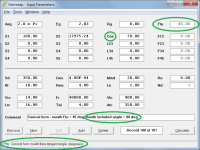
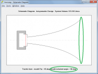
Fta is the flare tangent angle in degrees at a specified point along an axisymmetric horn. When shown on the Input Parameters window, it is the value at the horn mouth.
Attachment 1 shows a conical horn with a mouth flare tangent angle of 45 degrees, which means that the included angle of the horn is 90 degrees.
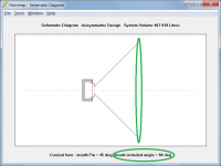
Attachment 2 shows the axisymmetric conical horn with the 90 degree included angle (i.e. a right angle).
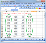
Attachment 3 shows an extract of the exported data for the conical horn. As expected, the Fta is 45 degrees at all points along the horn.
Attachment 4 shows a tractrix horn with a mouth Fta of 45 degrees.
Attachments
Greets!
Driver specs [2 mH Le assumed] not suited for a ~18-60 Hz pass-band, so FWIW: a mouth area to fit a 2x4 ft area and theoretically small enough to fit in your box with probably some room to spare for damping, mass loading, so quite a bit bigger than JAG's with of course a bit more output, lower CR, group delay, etc., due to more acoustic damping, larger rear chamber.
Note that pass-band ripple will be very muted in reality, though the room will chop it up pretty good.
GM
Fl and Fh are fine for a 18 - 60 hz bandwidth but you get weird results with Leach's math when requesting that bandwidth, a very low flare T and an enormous throat. But a 18 - 100 hz bandwidth looks great, a regular flare T and just a bit higher than 2:1 compression ratio (which would be less when folded as offset driver).
Regardless, your horn is better in every way than the one I posted. But it's almost 3x larger. Is that extra size worth it? If the wood was free (or at least cheap) and it was a permanent build in then maybe yes. But if it's meant to be mobile I would say absolutely not.
Here's a quick comparison, your design and mine overlaid. I changed your power to 1 watt and your Rg to zero to match mine and make things fair.
An externally hosted image should be here but it was not working when we last tested it.
Yours has a bit more sensitivity but it takes more excursion. Both are to be expected since yours is 3x larger.
Now here's what it looks like at claimed xmax with high pass filter in place. Both designs require a slightly different hp frequency, yours takes 700 watts to hit xmax, mine takes 1000.
An externally hosted image should be here but it was not working when we last tested it.
Your design will suffer less from power compression and is better in every single performance metric. But it's hardly practical and it doesn't beat the 3x smaller design by very much.
Having said that, I don't think OP is going to want an 18 hz horn after he analyzes his music. Unless he actively seeks out low bass music he probably won't have more than a couple of tracks that go anywhere near that low.
Fta is the flare tangent angle in degrees at a specified point along an axisymmetric horn. When shown on the Input Parameters window, it is the value at the horn mouth.
Attachment 1 shows a conical horn with a mouth flare tangent angle of 45 degrees, which means that the included angle of the horn is 90 degrees.
Attachment 2 shows the axisymmetric conical horn with the 90 degree included angle (i.e. a right angle).
Attachment 3 shows an extract of the exported data for the conical horn. As expected, the Fta is 45 degrees at all points along the horn.
Attachment 4 shows a tractrix horn with a mouth Fta of 45 degrees.
I thought FTA was something like that but the fact that only a round conical horn has a constant flare angle tripped me up. I didn't realize it was only reporting the flare angle at the mouth.
So is there any practical use to this info? It would only seem to appear to apply equal aspect ratio horns (like round), and even then only at the mouth (unless it's conical). What would this data be used for?
Last edited:
Greets back at ya GM! You too David, thank you for explaining FTA. And definately a bunch more thanks for Hornresp!
There is a lot to consider here, I really appreciate everyone contributing.
I did another sim last night too, this one is getting large at about 930 liters. Still not much to look at considering its size. There is a nagging sag in response at 24 hz that I didn't try to do much about. Upper extension may have improved a bit but still it isn't looking rosy. Sensitivity is less than desired as well.
Maybe its time to consider something else to see how they compare. I guess if this type of horn is my best option then I'll build one, but if a tapped horn or other horn sims better then I'm all over it.
And yeah, I'm certain I have some sub 20 hz music in my collection. Not many, but Pink Floyd - Dark Side of The Moon comes to mind. A few others if I dig a bit, but hey, I've lived fine without subsonics so if its impractical to build then its on to something else that performs better above 20 Hz with better sensitivity!
What do you think JAG, tapped horn maybe? I'll try it I guess... after my nap.
Attachments

There is a nagging sag in response at 24 hz that I didn't try to do much about.
Increase the closed rear chamber volume and that sag will go away. Anyway, simulate it with the high pass filter in place. The sag won't look so bad with the hpf. If you still don't like the look of it go ahead and make the chamber bigger. But remember, that rear chamber is keeping excursion in check so proceed with caution.
Sensitivity is less than desired as well.
The only thing that will increase the low frequency sensitivity is to increase the volume of the horn. A lot.
And yeah, I'm certain I have some sub 20 hz music in my collection.
Did you analyze the tracks to make sure?
Last edited:
- Status
- Not open for further replies.
- Home
- Loudspeakers
- Subwoofers
- FLH design basics for a dummy