That would be good and your reasoning is what I'm after to build actually. Could be a problem with quality at lower levels maybe... In my case I think I could do with some implied limit wrt high sound pressure. I will not do close mic'ed bass drums or aeroplane engine from 1 meter 🙂
But gain structure/position is interesting here for sure.
//
But gain structure/position is interesting here for sure.
//
Yes of course. The point is not to change the gain, but you'd still want to know what the fixed gain needs to be not to clip, but also not to bury the bottom of the mic's range in the ADC noise. As noted by TNT, that might be a 6dB gain with his mics.Whatever the microphone can handle, the microphone + recorder can handle without any need to change the gain.
I'll have a look at the audio files tomorrow. The stats published look a lot less dynamic than I would expect. Perhaps it just a different analysis.
Analysis is from my DAW "Amadeus Pro" for Mac. Here is an other one which sound to have a great dynamic range... figures for the excerpt.
Minimum sample value -1.0000 -1.0000
Maximum sample value 1.0000 1.0000
Peak amplitude -0.0 dB -0.0 dB
DC offset 0.0000 -0.0001
Minimum RMS power -44.4 dB -43.1 dB
Average RMS power -16.7 dB -15.1 dB
Maximum RMS power -5.5 dB -4.4 dB
Clipped samples 552 1601
//
Minimum sample value -1.0000 -1.0000
Maximum sample value 1.0000 1.0000
Peak amplitude -0.0 dB -0.0 dB
DC offset 0.0000 -0.0001
Minimum RMS power -44.4 dB -43.1 dB
Average RMS power -16.7 dB -15.1 dB
Maximum RMS power -5.5 dB -4.4 dB
Clipped samples 552 1601
//
Attachments
Yes of course. The point is not to change the gain, but you'd still want to know what the fixed gain needs to be not to clip, but also not to bury the bottom of the mic's range in the ADC noise.
Both of which you can calculate when you have the specifications of the microphone and the ADC, see posts 4, 5 and 7.
Last edited:
May I calculate what sound pressure equates the self noise of the mic?
Like compared to what we call silence 0 dB...
//
Like compared to what we call silence 0 dB...
//
I made it to 12 dB - feel its wrong... 🙂
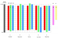
But if so, see the playing field below (bars to scale!)
Not much in it? A 130 dB range buffer might not be so easy...?
//
But if so, see the playing field below (bars to scale!)
Not much in it? A 130 dB range buffer might not be so easy...?
//
Attachments
Last edited:
The datasheet specifies the microphone's noise to be equivalent to 18 dB A-weighted, how do you calculate 12 dB?
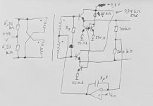
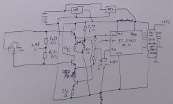
Regarding the buffer, the simplest circuit I could come up with is attached. As you don't want capacitors in the signal path, a transformer has to be used for common-mode level shifting. It also provides some analogue anti-aliasing filtering, as audio signal transformers don't have a flat response up to 5.5 MHz (assuming a sigma-delta sample rate around 5.6 MHz). Neither have microphones, by the way, so any 5.5 MHz or higher is likely to be caused by crosstalk rather than by sounds. The transformer also transforms the voltage up by a factor of two.
The buffer consists of two emitter followers, so it works completely in class A. Using low-base-resistance transistors, the noise will be negligible.
The op-amp and capacitor are part of a common-mode loop. Ideally they don't need to handle any signal.
Needless to say, the circuit has not been tried or tested and details like base stoppers and decoupling are missing. If the emitter followers need base stoppers, lossy ferrite beads will produce less audio noise than resistors.
Attachments
Last edited:
The datasheet specifies the microphone's noise to be equivalent to 18 dB A-weighted, how do you calculate 12 dB?
Hehe.... well sometimes on surprise oneself... :-/
I see it now 🙂 thanks!
Updated scart. Thanks för the schema - I will study it.
I'm in possession of 2 pcs of http://www.lundahl.se/wp-content/uploads/datasheets/1588.pdf
Maybe they can come in handy.
I would have liked to omit both trafo and caps but maybe its not possible...
//
Attachments
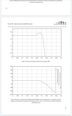
I would probably just set the ADC to 24/88,2 and leave it there - I want an analog pre filter to set in at say 24 kHz and the combo of analog input and digital filters should yield better than -150 dB at 44,0 Khz. Die alias, die 🙂
As you wrote in post #11, this will shift into the digital domain, into your custom decimation chain. The apodizing filter I use in my valve DAC is actually pretty close to setting in at 24 kHz and being at -150 dB at 44 kHz when the sample rate is 88.2 kHz. It neither interpolates nor decimates, but maybe a modified version of it, redesigned for two- or fourfold decimation, could be your last decimation stage. See Downloads | Linear Audio for details.
Attachments
Hehe.... well sometimes on surprise oneself... :-/
I see it now 🙂 thanks!
Updated scart. Thanks för the schema - I will study it.
I'm in possession of 2 pcs of http://www.lundahl.se/wp-content/uploads/datasheets/1588.pdf
Maybe they can come in handy.
I would have liked to omit both trafo and caps but maybe its not possible...
//
Those transformers should be well suited for the application.
You can't make an analogue filter without reactive (capacitive or inductive) components, but when you leave out analogue anti-alias filtering, you could in principle do without any capacitors, transformers or inductors in the analogue differential signal path by using a very awkward way of supplying the ADC chip. When you make a loop that senses the common-mode voltage at the microphone output and lifts the ADC ground and supplies until the common-mode reference from the ADC equals the common mode from the microphone, you can just DC couple them. If there are emitter followers in between, you have to add a 1 VBE offset somewhere. The outputs of the ADC can then be connected to digital isolator chips to get the digital signals near ground again. Internally, those chips normally use small capacitors or transformers, but at least those won't be in the analogue path then.
Many thanks for your interest and time. I was primarily thinking to get rid of serial caps as DC blockers. But I'm sure have some un-founded ideas about what matters or not... My thinking of having at least one LP filter before the ADC should be possible as a parallel cap - right?
As you might realise I would like a as clean signal path as absolutely possible between mic and ADC. If it was really short I wouldn't mind either. And I have no problem breaking "normal" or standards to achieve it.
I can only somewhat follow what you describe above but it sounds interesting. Now that we have got rid of the phantom voltage on the signal lines, I suppose you describe something else that need to be balanced out or compensated for, or?
Why/how come a common mode signal on mic output (indicating a differential interface?)?
As I understand it, these kind of mic just have a very simple 1 fet stage? So it outputs a single-end signal path!? But this contradicts the above I realise...
If one can assure no alias, I'm all about a none reactive signal path. Are aliases possible to combat digitally before the actual quantisation in an ADC?
//
I was still thinking about a microphone with a 3-pin XLR plug and the normal 48 V phantom supply connection. Are you referring to a hypothetical 5-pin custom-made microphone?
You can indeed make a low-pass filter with a parallel capacitor (or a series inductor).
You can indeed make a low-pass filter with a parallel capacitor (or a series inductor).
Last edited:
I'm seriously thinking about seeing to that my mic has extra wiring to feed the 48 volt supply they need.
Can you see a hinder for that to work?
Probably signal an DC feed need t share ground!? But not "hot"...
//
Can you see a hinder for that to work?
Probably signal an DC feed need t share ground!? But not "hot"...
//
I think you have to ask your microphone manufacturer if they can make a special version with separate supply and signal wiring and how much that will cost, or figure out what's inside the normal version and see if you can modify it yourself. As high-performance ADC chips normally have balanced inputs, it would be convenient (but not necessary) if your hypothetical microphone had a balanced output, like the standard version has.
Hi TNT. My Internet was out today, but it's now back on and I downloaded your files. It looks like mist of the tracks have enough- just enough - headroom. The Dans files does not and was badly clipped at the start. I suppose if you set the mic gain within the ADC range that will never happen.
I see average to peak differences of 16dB (Organ) to about 22dB on a couple of the tracks. That's typical of well mastered recordings, so you are already there.
The idea of this fixed gain recorder is very cool, will love to hear what you are able to do with it. 😎
I see average to peak differences of 16dB (Organ) to about 22dB on a couple of the tracks. That's typical of well mastered recordings, so you are already there.
The idea of this fixed gain recorder is very cool, will love to hear what you are able to do with it. 😎
Sketch of how you could interface a normal condenser microphone with 48 V phantom supply with an ADC chip without coupling capacitors or transformers. The ADC has lifted supplies (derived from a separate lifted battery) and a lifted ground. The op-amp has to be able to handle 48 V + tolerance, so it either has to be some exotic high-voltage type or a custom discrete design. Chances are you need some extra things to keep it stable.
Besides, I forgot to add anti-parallel diodes to protect the base-emitter junctions of the emitter followers against reverse breakdown. The same holds for the schematic of post #28.
Besides, I forgot to add anti-parallel diodes to protect the base-emitter junctions of the emitter followers against reverse breakdown. The same holds for the schematic of post #28.
Attachments
Last edited:
Thanks for checking them out Pano! What I use to do, despite of available gain knobs is that I deliberately set the gain quite low, used 24 bit recording and planned to gain up by just shifting out MSBs to get higher levels out of the recording. One leave all LSB below intact and suck in zeros from below. Having 24 bits to play with and that you typically get within 2 bits it has worked quite well. I realise the "Dans" track was probably robbed by one bit to much (its my sister singing and she wanted a little hotter mp3 to send around) - but it becomes a question of 6 dB which is quite a lot after all. Statistically I should end up with an average of 3 dB loss (1/2 a bit) over many recordings - thats OK with me 🙂
//
//
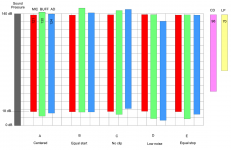
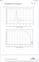
Pano, did you ever use "MasVis"? Its an wav file analysis program: MasVis - Ljudtekniska Sällskapet
Here are the results from some of the files...
//
Here are the results from some of the files...
//
Attachments
Graph explanation:
MasVis - Graphs - Ljudtekniska Sällskapet
+ online web version (click uploaded song for detailed view + possibility to download graphics)
MasVis online
//
MasVis - Graphs - Ljudtekniska Sällskapet
+ online web version (click uploaded song for detailed view + possibility to download graphics)
MasVis online
//
Last edited:
- Home
- Source & Line
- Digital Line Level
- Fixed gain field recorder?