I'm continuing to dig into the idea of a 100W amp using a J2-esque VAS and F4/BA3 OAS.
To get to 100W with a bit of headroom I'm going to need 35V rails. No problem on the F4/BA3 OAS where I can just drop the JFET input buffer.
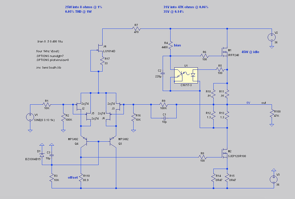
More of a problem for the J2 topology. Adding some resistors (before the current source and inside the LTP) gets the voltages down:
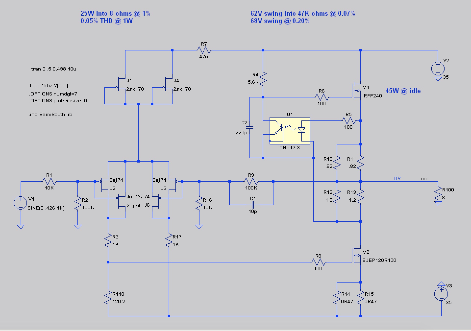
but of course adds a bit of distortion.
1) What do you call the process of adding these resistors? Is it "loading"?
So then I replaced the two LTP resistors with cascodes:
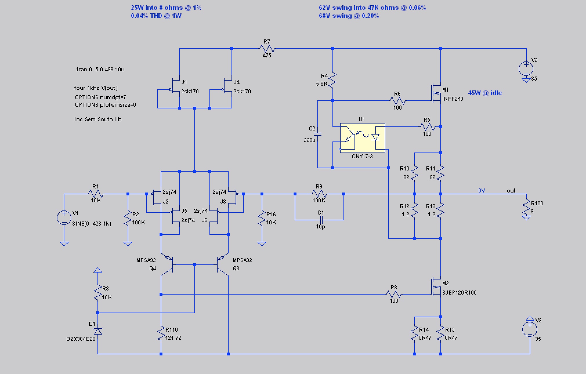
which corrects the distortion problem.
2) Is this the "right" way to go?
3) Is there any advantage to using JFETs for the cascodes?
4) My bias stage for the cascodes is pretty "dumb". But is that's all that's needed?
Sorry for the noob questions, but I'm sort of chuffed that I've gotten this far. 😉
Cheers,
Jeff.
To get to 100W with a bit of headroom I'm going to need 35V rails. No problem on the F4/BA3 OAS where I can just drop the JFET input buffer.
More of a problem for the J2 topology. Adding some resistors (before the current source and inside the LTP) gets the voltages down:
but of course adds a bit of distortion.
1) What do you call the process of adding these resistors? Is it "loading"?
So then I replaced the two LTP resistors with cascodes:
which corrects the distortion problem.
2) Is this the "right" way to go?
3) Is there any advantage to using JFETs for the cascodes?
4) My bias stage for the cascodes is pretty "dumb". But is that's all that's needed?
Sorry for the noob questions, but I'm sort of chuffed that I've gotten this far. 😉
Cheers,
Jeff.
Attachments
better to leave J2 thread and to bring it in separate one
I don't feel comfy contemplating here , everything being connected to eventual original , considering that my brothers from southern hemisphere are still in demand of original FW J2 , so Pa didn't publish sch
yeah , cascodes are proper way to shield input JFets from excessive voltage
no , I'm not finding JFets any better as cascodes
voltage bias point for cascodes is not so critical , however , it's useful to filter it somewhat - put small cap across zener ...... say 10uF or so
100 watts is 40 volt peak output.
Should have been more specific: it's for my Maggies (4 ohms nominal).
I'm trying to match my Rogue Cronus Magnum. (It's transformer-coupled so I think that means the 100W output is constant off of either tap -- 4 or 8 ohm?)
oh yeah , cap across zenner ........ but when I typed , I didn't realized that you misplaced things slightly
replace places of zener and resistor - cascode needs to be referenced to gnd , not to rail
take a look in my Babelfish J thread ...... I'm using LED string instead of zenner , but principle is the same
replace places of zener and resistor - cascode needs to be referenced to gnd , not to rail
take a look in my Babelfish J thread ...... I'm using LED string instead of zenner , but principle is the same
Biasing to ground does seem like a better idea, and I added the cap.
Thanks for the reference to the Babelfish J thread. Given the similar topology I think I need to study it more.
But I noticed you used a JFET CCS rather than a resistor in the Babelfish J cascode bias. SPICE gives the same numbers for either: did you go with the CCS just to "be sure to be sure" (as the Irish would say), or is SPICE not quite sophisticated enough to model the difference?
For those following along at home, ZM's Babelfish J PDF can be found at the bottom of this post:
About possible Babelfish J interest.
well , Spice is certainly smarter than me 🙂
I just liked that way ....... it doesn't matter that in logic and on paper and in sims - CCS is better than plain resistor
though - do not expect to see difference between these two in amp's THD
that's "just" cascode voltage reference ........ it's relatively easy to get it right
I just liked that way ....... it doesn't matter that in logic and on paper and in sims - CCS is better than plain resistor
though - do not expect to see difference between these two in amp's THD
that's "just" cascode voltage reference ........ it's relatively easy to get it right
One more dumb question: the 2SJ109s (in theory) have a well-matched pair inside.
Which is more important: good matching between the two JFETs sharing current on one side of the LTP, or good matching between the two sides of the LTP?
Which is more important: good matching between the two JFETs sharing current on one side of the LTP, or good matching between the two sides of the LTP?
Papa is cheating 🙂
not using one 2SJ109 as one side of LTP , but as left and right side of LTP
that way , two so-so matched 2SJ109 ,in parallel, are forming perfectly matched left and right side of LTP
not using one 2SJ109 as one side of LTP , but as left and right side of LTP
that way , two so-so matched 2SJ109 ,in parallel, are forming perfectly matched left and right side of LTP
Dear JeffYoung,
Since you are not opening your own thread I will post my un-scholarly recommendation here, even if this makes ZM mad 😀
If you use JFETs for your "cascodying" with gate tied to respective inputs, you have a bootstrap (signal to gate) and, provided the right gain (I imagine) you could end with a better sounding input section. That is my humble experience.
If you go there, you will be one step behind my future project of the "boostrapped-compound CFP" 😉 which, again, sounds better to me. But, hey! I could be well fooling myself... 😀
Why make it simple if you can complicate things and life?
Best wishes,
M.
3) Is there any advantage to using JFETs for the cascodes?
Since you are not opening your own thread I will post my un-scholarly recommendation here, even if this makes ZM mad 😀
If you use JFETs for your "cascodying" with gate tied to respective inputs, you have a bootstrap (signal to gate) and, provided the right gain (I imagine) you could end with a better sounding input section. That is my humble experience.
If you go there, you will be one step behind my future project of the "boostrapped-compound CFP" 😉 which, again, sounds better to me. But, hey! I could be well fooling myself... 😀
Why make it simple if you can complicate things and life?
Best wishes,
M.
Hi Max,
I don't think I'm following. If I apply the +/- signals to the gates of a pair of P-channel JFETs in the legs of the LTP then I'm just moving the voltage drop to them; they're not acting as a cascode anymore. So I imagine that's not what you meant.
I then noticed that you mentioned a complementary feedback pair, so I tried putting N-channel JFETs in the legs and biasing their gates at 15V below the signal, but I didn't make much progress getting that to work either.
Can you say a few more words regarding what you had in mind?
Cheers,
Jeff.
I looked in my drawer and my SJ109s are 14mA. I believe I want to run them near their IDss (as they're more linear there), which means I'm going to need 5 or 6 SK170 BLs to feed them. Not good.
But of course Nelson is just using SK170s here because he has them in a drawer. It's "just" a current source, and won't much affect the sound, right?
So what do I have in my drawer? Ahh... some Loveltechs. I think they'll need a current limiting resistor on their source, but that still gets the parts count back down to 2.
How's this look:
Attachments
You will want to test those LU1014's for breakdown voltage - they are
rated at a minimum of 24V.
rated at a minimum of 24V.
CCS is CCS
no use of making it Kosher , especially in case when you're making it worse than original
in that position - change of CCS is not resulting in change of sound , except in case when you make much worse CCS
once , when CCS is good enough , there is no influence on sound
no use of making it Kosher , especially in case when you're making it worse than original
in that position - change of CCS is not resulting in change of sound , except in case when you make much worse CCS
once , when CCS is good enough , there is no influence on sound
Hi Max,
I don't think I'm following. If I apply the +/- signals to the gates of a pair of P-channel JFETs in the legs of the LTP then I'm just moving the voltage drop to them; they're not acting as a cascode anymore. So I imagine that's not what you meant.
I then noticed that you mentioned a complementary feedback pair, so I tried putting N-channel JFETs in the legs and biasing their gates at 15V below the signal, but I didn't make much progress getting that to work either.
Can you say a few more words regarding what you had in mind?
Cheers,
Jeff.
Oh. I didn't want to go there so soon as I am busy. Maybe I will be able to simulate something. My own amp is much simpler because it is AC coupled so I simply pasted two blocks...
Cheers,
M.
You will want to test those LU1014's for breakdown voltage - they are
rated at a minimum of 24V.
With the 470R resistor above it the LU1014 is seeing at worst 21.5V.
Or are you saying they might not be up to spec?
...no use of making it Kosher , especially in case when you're making it worse than original
Why is it worse? I'd rather not have to use 6 SK170s per channel....
- Home
- Amplifiers
- Pass Labs
- FirstWatt J2