I have the PCB's assembled and was going through a final check of my work, and the CNY17-3 wiring in the circuit has me confused. What is the base of the transistor (pin 6) connected to? The schematic makes it look like pin 6 is connected to the body of the CNY17-3, without any connection to the circuit.
Attachments
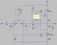
base of optotransistor is connected to optodiode, by light
leave base pin floating
leave base pin floating

Thank you Zen Mod! When I looked at the datasheets for Vishay, Lite-on and Fairchild, it confused me even more.
VISHAY: Has the base connected to pin 6, yet the schematics shown for testing shows the optodiode connection.
Lite-on: Has no connection between the base and pin 6
Fairchild: Shows the base connected and NOT connected to pin 6 based on part number.
VISHAY: Has the base connected to pin 6, yet the schematics shown for testing shows the optodiode connection.
Lite-on: Has no connection between the base and pin 6
Fairchild: Shows the base connected and NOT connected to pin 6 based on part number.
Fake lines for Pin 6 of the optocoupler on boards are very common........and the Gods are laughing about me poor cloner.....
:—))
:—))
Hi Elwood, double the J-Fets at the inputs to get more open loop gain. Look at this picture at 6moons....I have the PCB's assembled and was going through a final check of my work, and the CNY17-3 wiring in the circuit has me confused. What is the base of the transistor (pin 6) connected to? The schematic makes it look like pin 6 is connected to the body of the CNY17-3, without any connection to the circuit.
https://6moons.com/audioreviews/firstwatt10/open2_big.jpg. Two 2SJ109 in parallel.
What's DiAna. I really want to get a distortion analyzer but am cluless.I’m using DiAna with a focusrite interface to analyse the harmonic spectrum of the amp in vivo. Here’s the result before I inverted the input and speaker output of the amp to reverse the phase of the 2nd harmonic. It seems to do a good enough job to help tweek the amp
What's DiAna. I really want to get a distortion analyzer but am cluless.
Download link and everything you need to know to use it are on this page.
https://www.data-odyssey.nl/Diana.html
Hubert
(Damn tech, quoting failed  ), but to audiosteve:
I am hopelessly old fashioned, but I really like the HP334A. All you need is that, a scope, and some sort of signal generator (does not have to be noiseless to do simple residual waveform analysis and adjustments). Of course, it does not provide the whole thd spectrum (FFT), and since they are very old you need to take care when obtaining one, but the 334 or the likes will give you a live analog waveform and I kinda like that 🙂
Attached is an example (yes, posted before). In blue is the residual from the F2J @ 1W into 8R. It has a bit too much zoom compared to the fundamental, but you get the picture: very clean residual, just what we are hoping for from a no feedback single ended amplifier.
Noise along the residual curves I attribute to my own test setup and a signal generator just about to explode (yes, it did explode, or at least a few caps did).

), but to audiosteve:I am hopelessly old fashioned, but I really like the HP334A. All you need is that, a scope, and some sort of signal generator (does not have to be noiseless to do simple residual waveform analysis and adjustments). Of course, it does not provide the whole thd spectrum (FFT), and since they are very old you need to take care when obtaining one, but the 334 or the likes will give you a live analog waveform and I kinda like that 🙂
Attached is an example (yes, posted before). In blue is the residual from the F2J @ 1W into 8R. It has a bit too much zoom compared to the fundamental, but you get the picture: very clean residual, just what we are hoping for from a no feedback single ended amplifier.
Noise along the residual curves I attribute to my own test setup and a signal generator just about to explode (yes, it did explode, or at least a few caps did).
Last edited:
What Idss is needed for the front end jfets?
Do you need to match in any way the vgs of the mosfet with that of the sjep?
Do you need to match in any way the vgs of the mosfet with that of the sjep?
Which J2 clone circuit?
What Idss is needed for the front end jfets?
I seen also a version with double the jfets in the fe. What idss figures are used there?Which J2 clone circuit?
Hi, I just found out I have some in my drawer some of ECW20P20, it should be beautifull to use them in J2 project.
There is sombody that can simulate in LTspice?
There is sombody that can simulate in LTspice?
P channel part; J2 is having N channel in OS
you need entire amp flipped vertically in mirror
besides, xconductance of part is lowish ...... thus OLG decreased, resulting in lesser NFB, THD rises
not bad thing per se , just saying
you need entire amp flipped vertically in mirror
besides, xconductance of part is lowish ...... thus OLG decreased, resulting in lesser NFB, THD rises
not bad thing per se , just saying
- Home
- Amplifiers
- Pass Labs
- FirstWatt J2