
"DIY" is defined by the DIYer. To some, maybe it means hand-laying fiberglass substrate for the PCBs. Or heck, you can do your own silicon these days. Who are we to say what it involves?

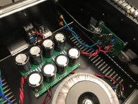
My J2 is finally up and running! J2 Pcb from EUVL, psu updated and beefed up with Jeff Young pcb, jfet from Punkydawg, on the output IRFP150 and most of all the SS generously given by Mr Pass last year. It’s running at 1.35A at this time.
I have been listening to the M2 and the Vfet part 2 for most of the last year and I must say that the J2 is sounding really really good. Nice extended bottom end, super sweet extended top and a quite a lot of power.
I was finding the J2 to sound a little muffled and flat at first, but after testing it with DiAna for the phase of the second harmonic I’ve realized that I was listening to the amp with a positive phase second harmonic. I’ve reversed the polarity at the input and output and now I have the negative phase second harmonic. I can’t believe how big of a difference that make!
Question : I know there is some people that have altered the ratio of the resistors on the output to get the right 2nd harmonic phase. Is there a real difference between what I have done the get the negative phase and changing the resistor ratio?
Attachments

J2's use the SemiSouth R100 SiC power Jfets. Their character is different from the IR Mosfets,
and I am not assuming that the rest of the circuitry is identical to the original either.
If you want negative phase 2nd, you would start by decreasing the gain of the mu follower on
the positive side and decreasing the degeneration on the negative output device.

and I am not assuming that the rest of the circuitry is identical to the original either.
If you want negative phase 2nd, you would start by decreasing the gain of the mu follower on
the positive side and decreasing the degeneration on the negative output device.
Thank you mr Pass for your answer and thank you again for the semisouth jfets 🙂J2's use the SemiSouth R100 SiC power Jfets. Their character is different from the IR Mosfets,
and I am not assuming that the rest of the circuitry is identical to the original either.
If you want negative phase 2nd, you would start by decreasing the gain of the mu follower on
the positive side and decreasing the degeneration on the negative output device.
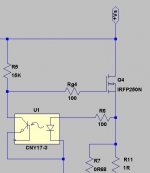
Just to be shure that I’ve got that correctly. Does increasing R5 on this partial schematics would reduce the gain of the mu follower? I already got the degeneration of the negative output device a little bit lower to 0R11
Hubert
Attachments
Nelson would
"If you want negative phase 2nd, you would start by decreasing the gain of the mu follower on
the positive side and decreasing the degeneration on the negative output device."
would that work on the AJ as well even thought there is no SemiSouth involved ? excuse my dumbness
"If you want negative phase 2nd, you would start by decreasing the gain of the mu follower on
the positive side and decreasing the degeneration on the negative output device."
would that work on the AJ as well even thought there is no SemiSouth involved ? excuse my dumbness
AJ allready has negative phase 2nd. But yes, if you decrease the gain of the Aleph CCS, you will increase the distortion.Nelson would
"If you want negative phase 2nd, you would start by decreasing the gain of the mu follower on
the positive side and decreasing the degeneration on the negative output device."
would that work on the AJ as well even thought there is no SemiSouth involved ? excuse my dumbness
But there might be other unwanted effects, Papa and Mighty can best tell you about that.
for EUVL's project, best to ask for specifics in EUVL's thread
maybe there is already answer
maybe there is already answer
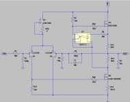
I am asking here because I’m using EUVL pcb to make my J2 inspired amp. I thought my questions were pretty simple and I was not referring directly to EUVL project. I’m a good builder but my understanding of the circuit is newbie level. I have already post on this thread and got great answers. Here’s the schematic on one of my post higher in this thread for reference Post 1951for EUVL's project, best to ask for specifics in EUVL's thread
maybe there is already answer
Hubert
🙂look like you mix too muchI am asking here because I’m using EUVL pcb to make my J2 inspired amp. I thought my questions were pretty simple and I was not referring directly to EUVL project. I’m a good builder but my understanding of the circuit is newbie level. I have already post on this thread and got great answers. Here’s the schematic on one of my post higher in this thread for reference Post 1951
Hubert
Seems like it 😅🙂look like you mix too much View attachment 1109832
But I’m just trying to better understand the circuit to make some ajustement to it. My amp is already performing perfectly fine. It’s been a year since I have read those two threads and ask those questions so my memory have some catch up to do 😉
If you adjust the ratio between the two power resistors in the positive current source you will get what you are looking for.
Their sum needs to remaIn the same (or close). If you really want to play, string a series of .1 ohm resistors to that sum and tap the output off the individual points. As the upper resistance increases the gain of the upper transistor goes down.
Their sum needs to remaIn the same (or close). If you really want to play, string a series of .1 ohm resistors to that sum and tap the output off the individual points. As the upper resistance increases the gain of the upper transistor goes down.
That all make a lot of sense. I will experiment around this and report back. From my ltspice simulation it seem like a small change can make a difference. Thank you again!If you adjust the ratio between the two power resistors in the positive current source you will get what you are looking for.
Their sum needs to remaIn the same (or close). If you really want to play, string a series of .1 ohm resistors to that sum and tap the output off the individual points. As the upper resistance increases the gain of the upper transistor goes down.
That all make a lot of sense. I will experiment around this and report back. From my ltspice simulation it seem like a small change can make a difference. Thank you again!
post exact schematic you're using, and I'll comment on that
btw. Babelfish J2 is far from original J2 schematic, even if some crucial values are xerox from Pa's ( no wonder)
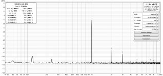
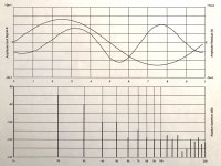
Oh thank you Zenmod! It’s running at 1.35A approx with standard fw psu. The 2nd harmonic is positive and I think it could be a little bit higher compared to the 3rd to be closer to the spec of the real J2.
Attachments
Last edited:
you also need small or bigger elco cap, connected across C-E of opto bjt
(maybe it is just missing on LTSpice schm, not in vivo)
anyhow - ref. to schm you posted, you need to obtain (0R4+0R5) sum of R11 and R13; so while you have sum of 0R9, vary their (R11, R13) ratio and you'll vary contribution of Mu follower in output signal
more for R13 (less R11) Mu is working more ......
when you're happy, stop and use these values for good
Pa gave you nice trick - for test - made that R11 of 4pcs of 0R1, then just tap output from various stages in 4*0R1 string ....... easypeasy
Ah exactly the help I was looking for. You’re right the cap is missing on my simulation. Now it will behave a little bit more like the real thing 😅 I don’t know how I could have missed this.. Thank you!
Next step, get or make a simple distortion analyzer. Spice is reliable, but the semis, not quite so much.
I’m using DiAna with a focusrite interface to analyse the harmonic spectrum of the amp in vivo. Here’s the result before I inverted the input and speaker output of the amp to reverse the phase of the 2nd harmonic. It seems to do a good enough job to help tweek the ampNext step, get or make a simple distortion analyzer. Spice is reliable, but the semis, not quite so much.
Attachments
- Home
- Amplifiers
- Pass Labs
- FirstWatt J2