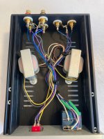
Hi adason, the little box on the right of the last picture has a pair of 1:8 turns ratio line level transformers in it, with a pot for volume control on the secondaries. The L and R channel primaries and secondaries are tied together at ground (grey-grey, brn-brn) but not to each other (e.g. the trafos are 'ground lifted' or isolating if I understand that term correctly). Tieing the secondary grounds probably destroys whatever potential the secondary outputs had for generating a balanced output? Maybe I'll try clipping the output ground leads where they're tied at ground, and try inputting that to the amp in balanced mode?Nice work ranshdow, enjoy!
If you come across good balancing transformer on the input, like i linked few posts back, do not hesitate to install on the input.
Now you are driving one side of the amp, grounding second half.
The one i linked is expensive, but has impressive parameters. There are many other balancing transformers available.
I was using this preamp for it's voltage gain. It's the only way I have currently to get usable volume out of my phone's headphone output.
Attachments

I think I've nailed it. A series crossover, where the tweeter sees amp + in series with an 8R levelling resistor and in parallel with a 0.33mH choke, and the mid-woofer follows in series, full open, connected to amp -, sounds pretty damn good. It brings up the mid-bass like heck, and it is in fact muddy and a touch floppy, but it's warm and full and really sings with RIAA equalization. Willie Dixon's Blues, Nina Simone on vinyl all sound wonderful. Current source is fun!!Per post #296, I have continued uncertainty as to how to rewire the crossover in my favorite 2-ways.
Maybe an RLC network as described in https://www.passdiy.com/project/amp...e-amplifiers-and-sensitive-full-range-drivers could tighten up the mid-woofer response?
Yeah, I woke up thinking about the resistor loading on either side of the OPT in an Arch Nemesis, how that alters damping factor. I've doubled the amount of acousta-stuff in the cabinets while swapping out the crossovers so that's also a factor.
So yesterday, I tried 50 ohms in parallel with the mid-woofer, and my quick impression was that it "sucked the life out of the music" so I pulled them out and went back to before. I think 22 ohms would be more severe, partitioning more of the current away from the mid-woofer, so I'm probably not going to explore that. Today I'm pushing the tweeter down in frequency, swapping the 0.33mH parallel inductors for 0.39mH. I like it better so far, but it's early days. This is expectation bias but the midrange is filled out more now. The A26RE4 mid-woofers do just fine driven full open.Maybe an RLC network as described in https://www.passdiy.com/project/amp...e-amplifiers-and-sensitive-full-range-drivers could tighten up the mid-woofer response?
As an aside, crossover calculations confuse me. This tweeter has a nominal impedance at 3kHz of ~6 ohms. A calculated 6dB high pass crossover for 3kHz and 6 ohms impedance calls for a 0.318mH coil. However, I have a 8.2 ohm leveling resistor in series with the tweeter, and if I do the calculation assuming a combined impedance of 14.2 ohms, the crossover point with a 0.33mH coil is 6.85kHz, way way high. I don't believe the tweeter is being crossed in that high.
I measured the actual impedance of a few of these 10W power resistors and they were all around 4uH, so I don't know how they would impede the AC much at all. So I'm ignoring the series leveling resistance in the impedance calculations for the LC network for now. If this is wrong, I'm all ears.
The way I understand series crossovers is that they act like a frequency dependent voltage divider (two voltage dividers in parallel, with their taps connected, in fact).
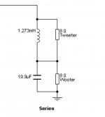
In the attached 1st order series crossover, in the top branch a LF/DC current will pass through the low resistance inductor unimpeded, bypassing the tweeter, but won't pass through the cap, so in the bottom branch it'll go to ground through the woofer, as intended. A HF/AC current in the top branch will not go through the inductor but will pass through the tweeter which has a much lower impedance, and it the bottom branch it'll get shorted to ground through the cap, bypassing the woofer. Somewhere in the middle the parts will all share some current.
So basically a frequency dependent series-parallel connected network of resistors. Change any one of them and you'll upset the whole interdependence.
In parallel crossovers this is not a problem and you can tweak each branch pretty much independently, but in series crossovers you'll have to view the network as a whole.
Attachments
Yes. The way I've started thinking about impedance is that it's the sum of a resistance and a reactance. Resistance is frequency-independent and effects all currents equally* while reactance is frequency dependent. The amount of current a parallel reactance will shunt for frequencies where it is not reactive thus depends on it's DCR.The way I understand series crossovers is that they act like a frequency dependent voltage divider (two voltage dividers in parallel, with their taps connected, in fact).
In the attached 1st order series crossover, in the top branch a LF/DC current will pass through the low resistance inductor unimpeded, bypassing the tweeter, but won't pass through the cap, so in the bottom branch it'll go to ground through the woofer, as intended. A HF/AC current in the top branch will not go through the inductor but will pass through the tweeter which has a much lower impedance, and it the bottom branch it'll get shorted to ground through the cap, bypassing the woofer. Somewhere in the middle the parts will all share some current.
*is this true?
Is reactance (and hence crossover frequencies) voltage dependent as well? My current conception is that reactance is not voltage dependent but this gets back to what is confusing me about the "R" in LC and RC calculations. I don't understand how a resistance that effects all current equally independent of frequency would matter in a frequency-dependent calculation.So basically a frequency dependent series-parallel connected network of resistors. Change any one of them and you'll upset the whole interdependence.
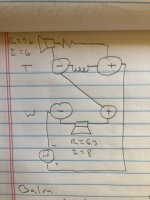
My understanding is that each and every part in a series crossover has an influence on the response of both (all) drivers. While the resistor R itself is virtually purely resistive, it's in parallel with a frequency dependent part (L), and will affect the circuit further downstream.
Imagine the series crossover at the intended crossover frequency with all the parts sharing some current. In this picture, with a resistance in series with the tweeter, applying a voltage across the crossover will result in reduced tweeter output due to less current going through the R+tweeter branch.
Due to the added R there will also be a bigger voltage drop developing across the upper half (L in parallel with R+tweeter). So compared to the situation without the extra R, there will be less voltage available across the lower half (C in parallel with woofer). The -3dB point (in case of a 1st order xo) of the woofer response will therefore also have moved.
I tried some math, and I think these changes can be relatively minor in the case of this series crossover where a low DCR coil is used. The tweeter portion of my series crossover has an effective resistance of 0.197 ohms (8.2 ohm resistor in series with the 4.6 ohm tweeter, both parallel to a coil with a DCR of 0.2 ohms). With a 12 ohm series resistor the math gives me the same effective resistance = 0.197 ohms. The woofer resistance is 6.3 ohms. Having that parallel coil seems to make the effect of the leveling resistor negligible to the total resistance of the top branch, and by inference, to the crossover network overall. It also implies very little power gets to the tweeter currently due to the tiny implied voltage drop across the tweeter network, and that it would be utterly fried if the coil went open circuit. 😱My understanding is that each and every part in a series crossover has an influence on the response of both (all) drivers. While the resistor R itself is virtually purely resistive, it's in parallel with a frequency dependent part (L), and will affect the circuit further downstream.
Imagine the series crossover at the intended crossover frequency with all the parts sharing some current. In this picture, with a resistance in series with the tweeter, applying a voltage across the crossover will result in reduced tweeter output due to less current going through the R+tweeter branch.
Due to the added R there will also be a bigger voltage drop developing across the upper half (L in parallel with R+tweeter). So compared to the situation without the extra R, there will be less voltage available across the lower half (C in parallel with woofer). The -3dB point (in case of a 1st order xo) of the woofer response will therefore also have moved.
Also I believe I have an answer to my earlier conundrum. The attenuation effects of an LC or RC are the sum of two attenuation curves- the linear, frequency-independent attenuation of the resistance and the non-linear, frequency-dependent attenuation of the reactance. Higher resistance lowers the linear contribution to a Bode plot, effectively pushing the knee of the non-linear portion out to higher frequencies.Is reactance (and hence crossover frequencies) voltage dependent as well? My current conception is that reactance is not voltage dependent but this gets back to what is confusing me about the "R" in LC and RC calculations. I don't understand how a resistance that effects all current equally independent of frequency would matter in a frequency-dependent calculation.
Attachments
generic/universal BJT is adequate
you can use practically anything
so yes for 951, but it is overkill - still better to use something with lesser power
you can use practically anything
so yes for 951, but it is overkill - still better to use something with lesser power
Is this 7 volt dependent on the supply voltage, i.e. with lower than the +-13.5 volt on the output this 7 volt lowers as well??caps at input are must - whatever you have for preamp, you don't want to fry it with amp (having 7V at input nodes)
Very likely a not very smart question ....
I would like to use some Black gates BP that can handle 6,3 volt at the input that is why I ask it anyway
Thanks
.......
I would like to use some Black gates BP that can handle 6,3 volt at the input that is why I ask it anyway
........
you wanna it short : toss that Drek to garbage bin, or clamp them as art installation to wall

if you're of medium age, you already don't have enough lifetime left, to finally get them burned in
so, just burn them and use Silmic bypassed with nice solid cap and be done
Harsh words... And I am way over medium age as well.
On the other hand I got them from my father who used them in a pre amp for 45 years. Would that maybe give some hope?
On the other hand I got them from my father who used them in a pre amp for 45 years. Would that maybe give some hope?
harsh words or not, but with age I have much less patience for BS spread by Audio Gurus
only what Mighty ZM is saying must be taken as Absolute Truth
OK, hand on heart, they're not bad sounding, but only after painstakingly long burning-in period ...... and even then they're not (bypassed or not) better than what I wrote in previous post
all in all - Fetish is not reason enough to change proper circuit - use caps adequate for voltage in specific position
(yeah, I have some small stash of BG caps, destined to eternal occupying of small drawer)
Thanks ZM! I really prefer an open mind and open ears over Fetish. But I will try them anyway and compare...
I do hope you keep those Blackgates of yours in the drawer under tension, just in case....
I do hope you keep those Blackgates of yours in the drawer under tension, just in case....
The issue of break in is 1 that I have been contemplating again, what actually happens in a cap that is breaking in?

- Home
- Amplifiers
- Pass Labs
- Firstwatt F1J