I replaced the 475R pot with a 1k5 pot and the 13.8V at the output were possible.
Is this o.k. without problems?
Is this o.k. without problems?
oh, how I like those Kosher improvements

if anything, IRF150 going down
up .......... well, ring of two with IRFP9240 is more than good enough
and yes, for Kosher parts with different Ugs, some fixing is expected
if anything, IRF150 going down
up .......... well, ring of two with IRFP9240 is more than good enough
and yes, for Kosher parts with different Ugs, some fixing is expected
No idea if F1J with SK and SJ sounds better than mine with IRFP240 and FQA12P20 but it's worth trying sometime.... might be the ultimate F1J.
Well, there it is. Thanks, ZM!no way
for CCS duty, IRFP are actually better than 2SJ200/2SK1530
I'll save the SK and SJ for other projects.
Because I have several well-matched 2sk / 2sj pairs and they have been unused for years. I don't have an IRF240 / 9240 anymore and I didn't want to order any more from Mouser. I'm very grateful to Gerd for helping me with a solution, the amplifier sounds incredibly nice on the Supravox 215 broadband speakers.well, I didn't read that post (#278)
what is damn improvement, making simple CCS-es with expensive mosfets???
Hello,My boards arrived today! Mouser order is on it's way. I am trying to decide what chassis to build it in, likely a 5U 300mm from the diyAudio store.
maybe you still have something to sell. I'm starting to make F1J. I have a 400VA transformer (hopefully enough), followed by PCB, R100 ...
So. I now have a partial kit with which to build an F1 clone in my hot little hands. I really don't want another amp with a Vishay IRFP MOSFET output stage, I have no onsemi power MOSFETs, and I certainly don't have a matched quad of SemiSouth power JFETs. What I do have is a matched quad of LD1014Ds and the little XRK boards to mount them. Adason seems to have had success using those little power JFETs as an output stage in his F1J. Before I burn (erm, commit) my precious quad, does anyone have opinions to offer? Should I hold out for some SemiSouths? I have a pair of Fostex FE126En drivers in BK-12m back-loaded horns so I at least have the right kind of speakers to play with a current source amp. The question to me is whether to commit to the rabbit hole of seeking of unobtainium devices for this little project.
I've got one, I love it, I listen to it almost nightly. It's my favorite, and it's why I'm considering the LD1014Ds in a completely different power amp topology.

I am going to choose to interpret this as an endorsement of these devices in this topology. Thank you!Then there is nothing stopping you to make f1j now.
I have a question about modifying my Seas A26 crossover for use with a current source amp. The voltage source crossover is shown below.
Is it a simple matter of putting the A26 woofer in series with the tweeter and it's crossover, or do I also have to move the high-pass network so it is in parallel with the T35 tweeter as well, instead of series as shown? I'm concerned that putting that capacitor in parallel is going to fail to keep the low frequency material from getting to and damaging the tweeter, as it looks to turn it into a conventional low-pass filter.
Is it a simple matter of putting the A26 woofer in series with the tweeter and it's crossover, or do I also have to move the high-pass network so it is in parallel with the T35 tweeter as well, instead of series as shown? I'm concerned that putting that capacitor in parallel is going to fail to keep the low frequency material from getting to and damaging the tweeter, as it looks to turn it into a conventional low-pass filter.
Attachments

F1-J build impressions
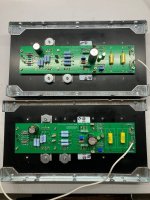
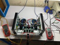
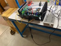
With encouragement from @adason, a nice UMS F1/F1J clone and PSU board set made by @csample, well matched JFETS and MOSFETS from @mbrennwa and @rhthatcher respectively, and circuit mod suggestions from those who participated in this thread, I got an F1J modified to work with LD1014Ds together & working on the bench. It sounds cool on my 4" Fostex full-range speakers, punchy and deeply detailed, and less shouty in the mid-treble than these speakers sound with other amps. Other than the god-awful turn-on thump that makes me want to add a speaker protection circuit, and a plan to rearrange the layout of the trafos and rectifiers in the chassis, I'd say this is going to be a success for me.
Details: pre-setting the P1 pots to ~1k, at first power there was ~13.5V at the speakers with 100-200mV of DC offset, easily dropped to 10-20mV by adjusting P2 without any additional resistors necessary. I dialed the bias down to 12.5V which gives a solid Vds on the LD1014Ds of 4.3V. Per @Zen Mod 's guidance I wanted this under 5V; the Vds goes up a bit with bias voltage. Also the rectifier heatsinks get warm, 50C, and even the smoothing caps in the PS get a little warm too. LD's get to 55C or so.
Per post #296, I have continued uncertainty as to how to rewire the crossover in my favorite 2-ways. It would be really simple for me to put the woofer and tweeter in series (woofer first to +, does this matter?) and to leave the tweeter's single pole high-pass capacitor and leveling resistor as they are, in series and between the woofer and tweeter.
Attachments
That's a really nice build, congrats!
Could you briefly summarize the changes to the circuit for using the LU1014D, if any?
And regarding series vs. parallel crossovers, take a look at https://sound-au.com/parallel-series.htm
Could you briefly summarize the changes to the circuit for using the LU1014D, if any?
And regarding series vs. parallel crossovers, take a look at https://sound-au.com/parallel-series.htm
Thank you! And, certainly:That's a really nice build, congrats!
Could you briefly summarize the changes to the circuit for using the LU1014D, if any?
And regarding series vs. parallel crossovers, take a look at https://sound-au.com/parallel-series.htm
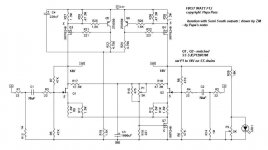
It starts with Papa's mods for the F1-J as documented in schematic edits by ZM (attached). However, csample's boards have additional mods, documented in his BOM excel which I only have on paper. There were comments in this thread as well:
- A 5k pot (P2) is put in series with R5, and R5 is 43K instead of 47K. R6-8 are modified to 47K per Papa's schm. P2 is used to make minor trim in the DC offset. I got lucky, my actives were super well matched so I was able to zero the DC offset without having to add any additional parallel resistors, which csample's boards provision for.
- P1, another 5k pot, is set to 1.05k before mounting. This gives an initial bias of ~13.5V.
- the zener protection diodes were eliminated. no jumpering as that would make a short to ground on the input
- the input coupling capacitance was 11uF. In my case I used a 1uF polypropylene cap in parallel with a 10uF nonpolarized electrolytic (Nichicon UES1H100MPM), which csample's BOM and boards also provision for.
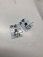
- For R1-R4 I used 100R, with R3-R4 mounted directly on the LD1014D adapter boards as SMTs, and the R3-R4 spaces on the PCB jumpered as they are in series with the input. I did this in part for convenience (I had SMT resistors in this value) and in part because it took about 220R of gate stoppage in my F3 to stop it from oscillating.
- Bias for SemiSouth JFETs is +14V. Adason liked lower values, and I'm chicken so I do too (currently +12.5V from speaker + to gnd, not to speaker -).
- Q1-Q2 and Q3-Q4 separately are Vgs matched.
- add jumper for single ended input
Attachments
Nice work ranshdow, enjoy!
If you come across good balancing transformer on the input, like i linked few posts back, do not hesitate to install on the input.
Now you are driving one side of the amp, grounding second half.
The one i linked is expensive, but has impressive parameters. There are many other balancing transformers available.
- Home
- Amplifiers
- Pass Labs
- Firstwatt F1J