To me how this stuff looks is very similar to the Aleph ccs. You have one modulation resistor(the one between the sources) and the other one that sets the ac gain.
as posted before Christmas... a compound transistor?
That implies a combination of a 'feedback' from the drain to the gate through the driver mosfet, maybe both sides - or just on the SIT side. Or only on the other side. Anyway . . . somewhat less simple.
That implies a combination of a 'feedback' from the drain to the gate through the driver mosfet, maybe both sides - or just on the SIT side. Or only on the other side. Anyway . . . somewhat less simple.
Attachments
That was before coffee... The ratio would have been 1:4, but now I am doubting myself.My guess: The Mosfet is connected through a resistor divider network to SIT and Output. Make this resistors ratio 1 : 5 and the Mosfet voltage contribution to the output should be five times less than that of the SIT. That is 20%…
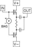
Both SIT source and MOSFET source produce output. No voltage gain, in phase, source follower mode. The two devices share their source resistor.
The additional RC between MOSFET source and Output adds impedance, making the Mosfet contribute less. Does it also allow the shared source resistor to correct errors? The circuit reminds me of feedforward cancellation. But that is normally used for identical devices, and here they are quite different. This is no feedback either as the output is not fed back to an input.
Pa is making us think...
He said it was fairly dumb, the last trick. What could it be? Maybe the fact that you can adjust the ac-coupled resistor on the fly without turning the amp off, and thus tune the output on the fly?

As you say, the network adjusts the ratio of the contributions of SIT and Mosfet.
The other more obscure part of the trick - imagine that the resistor in series with the
cap is zero, where the AC contributions approach 50/50.
Stan Ricker of JBL fame was a big fan of running his electrolytics back-to-back in series
with a charge applied between them so as to have them work push-pull AC with a DC
bias. This to reduce the distortion and also cancel the 2nd harmonic which would be the
dominant distortion.
In the diagram below, the output coupling caps have a DC bias and each carries the
bulk of the AC from their attached Fet, but in reverse phase. In this manner the 2nd
harmonic each would have is cancelled.
Also, the DC behavior of the Fets is governed by the resistor which degenerates and
stabilizes the DC bias while the AC behavior is undegenerated, allowing a wider Class A
operating region and better square law cancellation.
If you are operating push-pull followers with a single polarity supply this circuit has
something to offer, independent of the control of output ratios.
Attachments
Very clever trick.
What can you say about the temperature coefficients of the SIT and PFET? In particular, is any bias servo really needed since the source-to-source resistor helps to stabilize the bias current.
What can you say about the temperature coefficients of the SIT and PFET? In particular, is any bias servo really needed since the source-to-source resistor helps to stabilize the bias current.
You are right pa! I can do better, I just don’t know better….  Christmas is over and you are still working overtime
Christmas is over and you are still working overtimeThe Source to Source resistor tends to be large, so temperature coefficient is not a big issue.
This is the nicest one up to now!
I chose the Mosfet source resistor for equal contribution, thanks Nelson for explanation to this point, value is about 1R but must be outside the two caps point.
and second the biasing mechanism ZM found some time ago for DEFiSIT, see here
works like glue!
Having both contributions on same level, I inserted the 2R in the lower cap from Mosfet and it has now around 20%.
Current might be a bit low, how many do I need for 35W with 60V rail?
Happy thanks to Nelson and ZM!
I chose the Mosfet source resistor for equal contribution, thanks Nelson for explanation to this point, value is about 1R but must be outside the two caps point.
and second the biasing mechanism ZM found some time ago for DEFiSIT, see here
to save you from ghost chasing and give you some more time for quality staring at goats, which is much more beneficial for state of mind
at least I'm finding it that way
disclaimer - both DC offset and Iq stability are depending of hefty heatsinking, rail variance ( mains fluctuation) and hope that SIT in case is not having hungry gate
here is case one - SIT Ugs lower in number than P channel Mosfet Ugs, so SIT gate is higher than Mos gate, voltage vise
reckon that 2V5 voltage reference is covering most possible cases; if more is needed, there are ways for that too, easy to increase...
works like glue!
Having both contributions on same level, I inserted the 2R in the lower cap from Mosfet and it has now around 20%.
Current might be a bit low, how many do I need for 35W with 60V rail?
Happy thanks to Nelson and ZM!
Attachments
R2 in you case is not bypassed so
Try including the 2r resistor inside the loop and use 10r for the other resistor, see what you get.
The ac part of the above sence is not true in your case because you don’t have r2 bypassed.Also, the DC behavior of the Fets is governed by the resistor which degenerates and
stabilizes the DC bias while the AC behavior is undegenerated, allowing a wider Class A
Try including the 2r resistor inside the loop and use 10r for the other resistor, see what you get.
Ha, I misread as often. But that is imagination.as posted before Christmas... a compound transistor?
That implies a combination of a 'feedback' from the drain to the gate through the driver mosfet, maybe both sides - or just on the SIT side. Or only on the other side. Anyway . . . somewhat less simple.
ThePass: The interesting thing is the complementary circuit which biases the output SIT.
- Home
- Amplifiers
- Pass Labs
- First Watt SIT5