
So wait, does that mean I'm not supposed to believe what I read at Reno Hifi, or I'm not supposed to believe your post?!
😉
😉
Probably involving Tokins?I have a feeling that the next First Watt amp is going to blow our minds!
So wait, does that mean I'm not supposed to believe what I read at Reno Hifi, or I'm not supposed to believe your post?!
😉
I don't believe you that you're having a dilemma

The inventory of the SemiSouth R100 power Jfets is getting low. We still have enough for a few months production and then will have to preserve the remainder for service work. Unfortunately I haven't found a suitable replacement.
In any case the J2 has had a very long production life, much longer than originally intended, and the snail must keep moving...

In any case the J2 has had a very long production life, much longer than originally intended, and the snail must keep moving...
Maybe you should consider using the SJEPs only for the gain device, and a high Yfs MOSFET for the modulated current source.
That will double your number of production units.
2SK3163, 2SK3497, FQA19N20C, FQA28N15, ... the list is long. 😉
Cheers,
Patrick
That will double your number of production units.
2SK3163, 2SK3497, FQA19N20C, FQA28N15, ... the list is long. 😉
Cheers,
Patrick
Incidentally, 2SK3163 is NRND, which means still available.
https://www.renesas.com/us/en/produ...ingle-power-mosfet-60v-75a-75mohm-3p#document
And in stock at chip1stop for DIY quantities.
Of course Nelson could order thousands fom Renesas direct.
🙂
Patrick
https://www.renesas.com/us/en/produ...ingle-power-mosfet-60v-75a-75mohm-3p#document
And in stock at chip1stop for DIY quantities.
Of course Nelson could order thousands fom Renesas direct.
🙂
Patrick
Maybe you should consider using the SJEPs only for the gain device, and a high Yfs MOSFET for the modulated current source.
That will double your number of production
F8 does that already, but we are loathe to alter the Aleph J...
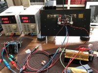
Based on Patrick's DC-coupled F8-style idea I decided to give it a try. I swapped the polarities to use SK170 instead of SJ74 and went for a latereral instead of the semisouth.
The amp is quite stable with cheap benchtop supplies:
10sec after start +27mV offset
1 minute +22,8
5 minutes +15,1
1 hour -12,7
Bias (~1.36A) changes max. 10mA after a hour (with respect to bias after 20sec). Gain is about 4.
My findings so far:
With 2SJ162/2x9240mCCS, 330R/91R NFB and 10,4mA 2SK170, 250m/687m Follower-R at 1% THD I get about 18W at 6R (10,4V) and 10R (13,5V) out of the amp (in each case visual clipping point). A later measurement confirms this points with ~ 1% THD.
Despite my noisy open bench test setup I measured 0,025% THD at 1W/6R/1kHz and 0,047% THD at 1W/10R/1kHz. At 10W I got 0,095%/6R and 0,21%/10R. FR shows -1dB at ~ 55kHz. All measurements have been done with a not so perfect 1:10 divider. Therefore I assume the bandwith in reality is higher.
What made me curios: in this setup I needed two Fets for the mCS to get the lower impedance "going". The gain device seems to have almost no impact on lower load impedances. In Nelson's F8 only one IRF is enough. Also LTspice predicts that one FET for the mCS is sufficient. What do I miss?
Happy diy'ing & THX to Patrick
The amp is quite stable with cheap benchtop supplies:
10sec after start +27mV offset
1 minute +22,8
5 minutes +15,1
1 hour -12,7
Bias (~1.36A) changes max. 10mA after a hour (with respect to bias after 20sec). Gain is about 4.
My findings so far:
- lower Idss JFET's only work slightly better outputwise, maybe ~100mV more Vrms out (tested 3mA vs. 10mA, tested also 7,3mA) before visual clipping.
- the transconductance of one 9240 for the modulated CS seems too low. two in parallel are needed to gain some headroom. Max. Vrms rises from ~9.5V (one 9240) to ~10,4 (two 9240) at 6R. so it seems the FET transconductance in the mCS mainly determinates the maximum power output at lower load impedances (as the 10R max. output doesn't change).
- the offset is way more stable with only one mCS FET (around half).
- the gain FET transconductance seems to mainly determinate the maximum power output at higher load impedances. The change from SJ162 to 9140 brought addional 700mVrms at 10R or ~ +2Watts (with no change at 6R) - based on visual clipping when looking on a scope.
With 2SJ162/2x9240mCCS, 330R/91R NFB and 10,4mA 2SK170, 250m/687m Follower-R at 1% THD I get about 18W at 6R (10,4V) and 10R (13,5V) out of the amp (in each case visual clipping point). A later measurement confirms this points with ~ 1% THD.
Despite my noisy open bench test setup I measured 0,025% THD at 1W/6R/1kHz and 0,047% THD at 1W/10R/1kHz. At 10W I got 0,095%/6R and 0,21%/10R. FR shows -1dB at ~ 55kHz. All measurements have been done with a not so perfect 1:10 divider. Therefore I assume the bandwith in reality is higher.
What made me curios: in this setup I needed two Fets for the mCS to get the lower impedance "going". The gain device seems to have almost no impact on lower load impedances. In Nelson's F8 only one IRF is enough. Also LTspice predicts that one FET for the mCS is sufficient. What do I miss?
Happy diy'ing & THX to Patrick
Attachments
-
 Spectrum 1W 6R.jpg149.2 KB · Views: 207
 -
 Spectrum 1W 10R.jpg149 KB · Views: 132
 -
 Spectrum 10W 6R.jpg150.3 KB · Views: 125
 -
 Spectrum 10W 10R.jpg150.7 KB · Views: 112
 -
 Harmonics vs Freq1W 6R.jpg153.4 KB · Views: 124
 -
 Harmonics vs Freq1W 10R.jpg147.7 KB · Views: 114
 -
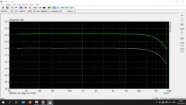 FR 1W 6_10R.jpg134.6 KB · Views: 196
 -
 IMG_3312.jpg583 KB · Views: 211
Based on Patrick's DC-coupled F8-style idea I decided to give it a try.
I swapped the polarities to use SK170 instead of SJ74 and went for a latereral instead of the semisouth.
Well, it is not a F8 anymore, but an inverted one.
More like a UDNeSS without diff pair :
https://www.diyaudio.com/community/threads/udness-or-you-dont-need-semisouths.343164/post-6655510
So maybe should discuss over there instead of poluting Nelson's forum.
You can do better with a Exicon double die (ECW20P20-S colour code red), than a single 2SJ162.
Or 2SJ618 if you can compensate for drift.
the transconductance of one 9240 for the modulated CS seems too low.
2SJ618 could replace 2x 9240's at 1.3A bias.
And Toshiba gives you more output headroom due to much lower Vgs.
With 2SJ162/2x9240mCCS, 330R/91R NFB and 10,4mA 2SK170, 250m/687m Follower-R at 1% THD ....
As discussed above, lower Idss is more advantageous.
For example 6mA.
What made me curios: in this setup I needed two Fets for the mCS to get the lower impedance "going".
The gain device seems to have almost no impact on lower load impedances.
You need to check how much the current sharing ratio changes with top and bottom.
Especially also with different loads.
You can do so by inputting a 100Hz sine wave at the input.
Then use a good, battery-powered, digital multimeter to measure the AC voltage across R3,4 in the simplified schematics.
https://www.firstwatt.com/pdf/prod_f8_man.pdf
Have you tested with a 10kHz square wave on a reactive load (e.g. 8R // 100n) ?
Patrick
The F8 is now discontinued, have we seen an original schematic or is it still a top secret document? 😎
if F8 is discontinued, just imagine what Papa is preparing .......

Who knows, could be F9 Cougar, F9F Panther or anything.... imagine what Papa is preparing ....

The reason to explain the discontinuation of the J2 and F8 is the end of the stash of power Jfet. So Idont think a J3. I vote for a SIT 4 with the big Tokins. But, is the regular Firstwatt chassis capable of dissipating enough heat to accommodate the big Tokins?
- Home
- Amplifiers
- Pass Labs
- First Watt F8