Voigt pipes. Was Dayton full range, but just added a 6.5" Peerless/Tymphany and HiVi SD1.1-A tweeter. No zobel or bsc. All still breaking in. I think they need a little back wall support, but it's very good so far. Very dynamic, needs a little bass, but what else is new. 🙂
I just enjoyed again the last two days the F7.
Meanwhile I have so many amps in the basement that I enjoy rotating.
This is always also the opportunity to retune the bias etc.
In the case of the F7 some remarks...
It sounded a bit muddy after I readjusted the 10db k2 over k3 and negativ k2 phase.
And indeed why ever, k2 was 12dB over k3.
The recommendation for 10db Nelson gave in the manual is probably related to 1W at 8 Ohm.
If you have less Watt let us say 3/4 Watt the k2 over k3 will be higher than 10dB, maybe 15 or even 20dB.
I suppose also the 10dB Nelson recommends is for medium speaker sensitivity let us say around 90dB. So it is no fixed value.
My Klipsch Forte II are around 95dB, so the k2 10db higher might be to much.
I went down to 8dB and was happy.
Of course the room is also a component that can make bass overload.
What I want to say, if you want to have the most pleasure with your F7, check the k2 over k3 and if your feel the sound is too dark and dirty and muddy, go down with the k2 to a lower value.
The k2 negative phase is still more suitable for too much darkness because the neg phase enforces this.
The F7 can be so airy!
Incredible but true, your hear 1db difference and only a Diyer can adjust the amp to fit best to the chain and the room and the speaker.
I hope I encouraged you to play around!
Hope I wrote no nonsense.
Just a question,Mr. Generg,what were the resistance values on the jfets at the 12db difference?I am interested to see if I can correlate sim results with actual measurements.
Last edited:
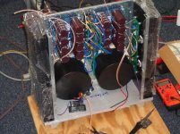
Schubert----(and Vince). Nice job on the amp.The supply looks like it will be rock solid.Is that a 4u or 5u case?
Just a question,Mr. Generg,what were the resistance values on the jfets at the 12db difference?I am interested to see if I can correlate sim results with actual measurements.
That will depend on idss values of each jfet as well as transconductance of each mosfet at the selected bias point.
Either use your ear or get hold of a distortion analyzer.
Also like brother generg said further tweaking may give more enjoyable results depending on your speakers as well as your personal taste.
Schubert----(and Vince). Nice job on the amp.The supply looks like it will be rock solid.Is that a 4u or 5u case?
4u. Not very hot at all with 1.2A bias.
Just a question,Mr. Generg,what were the resistance values on the jfets at the 12db difference?I am interested to see if I can correlate sim results with actual measurements.
As Pico says the resistance values of the pot at the J-fets depends on the IDss of the J-Fets chosen.
I took for the J74 a value 2mA higher than the k170 to get more in the middle of the pot.
Only with a distortion measurement by sound card you can see the k2 minimum and around this point you can adjust either the pos or neg k2 phase and the magnitude.
At the moment I even prefer only 7dB k2 higher than k3 and neg phase.
When you have the lowest k2 point adjusted you get the neg phase by increasing the resistance the k74 sees from the pot.
I doubt that you can do this by ear. You had to look for the brightest and bassless sound and then increase the resistance value for the j74.
And of course every change of the J-Fet source pot changes the offset and correcting the offset changes again the magnitude of k2.
So you have to do some work.... 🙂)
I used 7.6mA for 2sj74 and 7.9mA for 2sk170, thinking that would get me closer to the middle of the pot (maybe not?). I got a distortion minimum of sorts around 8dB (17:3 approx.; it was hard to measure the pot in the circuit). Changing the pot was a PITA because everything else changes as Generg says, and it didn't make much difference in the distortion measurements. My amp sounds a little darker than Vince's but it's far from muddy.
I think Oreo gave the best hint some pages earlier....
"I am using 11ma k170 and 13ma j74.To get the 10 db H2/H3 ratio my K170 degen r is 6 ohms,the J74 degen r is 14 ohms.With matched 8 ma jfets you need 1 ohm on the k170 and 19 ohms on the J74 to get the same result(H2/H3).So unmatched jfets are probably beneficial."
I had not his values but I kept the 2mA difference and succeeded to get the wanted k2 not at the outer end of the pot as before.
Thanks Oreo382!
I think Oreo gave the best hint some pages earlier....
"I am using 11ma k170 and 13ma j74.To get the 10 db H2/H3 ratio my K170 degen r is 6 ohms,the J74 degen r is 14 ohms.With matched 8 ma jfets you need 1 ohm on the k170 and 19 ohms on the J74 to get the same result(H2/H3).So unmatched jfets are probably beneficial."
I had not his values but I kept the 2mA difference and succeeded to get the wanted k2 not at the outer end of the pot as before.
Thanks Oreo382!
The values I wrote here were from my simulations, not from actual measurements.But it looks like the sim is probably pretty close to actual from what you have said here. Thanks for your reply.
Dang. I missed that one. Maybe I'll go back and change out the sj74's for a higher value....some day.
Last edited:
@oreo
Funny, so you seem to have a very good Spice simulation.
Can you build different Idss values?
Funny, so you seem to have a very good Spice simulation.
Can you build different Idss values?
@oreo
Funny, so you seem to have a very good Spice simulation.
Can you build different Idss values?
Yes I can.I've done it with 8 ma pairs as well as 13 and 11 ma as my amp is.Also used Ian Hegglun's temperature compensated mosfet models(75 & 25 celsius).The results at different temps are quite different as far as harmonics vs. jfet resistance settings go. I've got a few with different jfet source resistor combos.I need to build a sound card probe to be able to compare sim vs actual,I do have a signal generator.Interestingly I have done these sims with an 8 ohm load,4 ohm and also a sim of my loudspeaker crossover and drivers simmed as simple inductors with resistance.With that model the 3rd harmonic is completely suppressed,leaving only the second harmonic.I have no clue how accurate this all is but I find it interesting at least.After all I am just a backyard mechanic with this audio stuff.
Oreo382
Your sims have always been better than my listening and adjusting method. After your recommendations, I don't feel the need to monkey around any further.
Thanks
Vince
Your sims have always been better than my listening and adjusting method. After your recommendations, I don't feel the need to monkey around any further.
Thanks
Vince
Oreo382
Your sims have always been better than my listening and adjusting method. After your recommendations, I don't feel the need to monkey around any further.
Thanks
Vince
🙂
I used 7.5mA k170 and 9.5mA J74 and had the wanted 10db neg phase no more at the pot end but more in the middle.
With two 8.5mA I had to go the total end of the pot.
With two 8.5mA I had to go the total end of the pot.
I used 7.5mA k170 and 9.5mA J74 and had the wanted 10db neg phase no more at the pot end but more in the middle.
With two 8.5mA I had to go the total end of the pot.
The 8.5 ma jfet results you got correlate very well with my simmed results. I think I had values of 1 and 19 ohms to get the 10db difference with 8ma jfets.
I used 7.5mA k170 and 9.5mA J74 and had the wanted 10db neg phase no more at the pot end but more in the middle.
With two 8.5mA I had to go the total end of the pot.
I hope you're seeing that on a CRO.
That's all I'm going to say.
- Home
- Amplifiers
- Pass Labs
- First Watt F7 review